©2013 PACE Inc., Southern Pines, NC
Page 17 of 31
All Rights Reserved
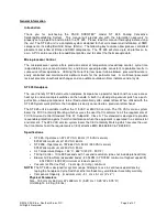
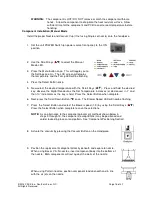
When using a Curved, Single Jet nozzle, position the component on its
land pattern (prefilled or with solder paste deposition). Solder tack
lead(s) if necessary.
10. If using a Single Jet nozzle proceed to step 15.
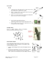
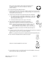
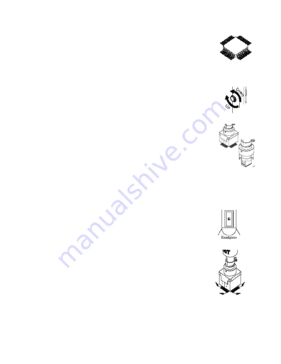
11. Using the Vacuum Pick Adjust Control on the handpiece, adjust the vacuum cup to a point
where the bottom of the vacuum cup touches the component body. The component is now
held in position with the vacuum cup.
12. Using the Vacuum Pick Adjust Control, adjust the position of the component:
a) To an approximate distance (depending on component) of 1-1.5mm (.040-
.060”) between the bottom of the component and the bottom of the nozzle
when using a Box or Pattern nozzle.
b) Contacting the BGA component when using a V-A-N nozzle.
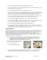
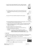
13. Lower nozzle (with component) to a point where the component
leads/contacts rest gently on or just above the component land pattern.
NOTE:
If component has been pre-positioned on land pattern, lower nozzle
to desired height above PCB. A height of 1-1.5mm (.040-.060")
above the PCB when using Box or Pattern nozzles is recommended.
14. Ensure that the handpiece is held vertical to the PCB (except with Single Jet
nozzles).
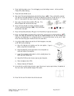
15. For Single Jet nozzles, hold the end of the nozzle tube above the rework area at a height and
angle which gives the best results in your particular application.
NOTE:
Any required preheating should be completed before advancing beyond this point.
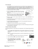
16. Press and hold the Handpiece Switch to activate the heat cycle.
(Heated air is now being applied to the rework area)
17. If using a Single Jet nozzle in a hand held operation, move the handpiece as necessary to
direct air flow to the solder areas requiring reflow.

