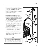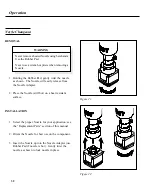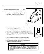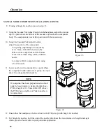
Figure 15.
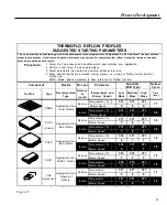
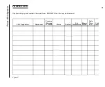
THERMOFLO REFLOW PROFILES
SUGGESTED STARTING PARAMETERS
This chart provides a base starting point for the development of exact parameters ("Established Profile Guidelines") for your surface
mount rework process. Initial tests using these references may not result in complete solder reflow. Adjust the reference values as
necessary to obtain desired results.
Procedure:
1.
2.
3.
4.
Select the Component and Substrate which best matches your application.
Perform a test using the base parameters.
Adjust parameters as desired and perform aditional test runs.
When desired results are achieved, record process on a copy of Profile Control Chart or
Profile Log.
NOTE: Blower Speed parameter is base reference for Reflow function.
Component
Nozzle
Process
Parameter
Substrate
(PCB Type)
Reflow
Cycle
Outline
Type
Recommended
Type
Remove
or
Install
(Temperature and
Blower Speed)
Low
Mass
Medium
Mass
H igh
Mass
Time
(sec.)
PBGA
Appropriate Size
V-A-N Nozzle
Remove
Temperature (°C)
371
371
371
77
Blower Speed
5
5
5
Install
Temperature (°C)
371
371
371
90
Blower Speed
3
3
4
PLCC
(J Lead)
Appropriate Size
Box Nozzle
Remove
Temperature (°C)
371
371
371
30
Blower Speed
7
8
8
Install
Temperature (°C)
371
371
371
30
Blower Speed
7
8
8
PQFP
Appropriate Size
Box Nozzle
Remove
Temperature (°C)
316
371
371
18
Blower Speed
6
7
7
Install
Temperature (°C)
316
371
371
18
Blower Speed
6
7
7
SOIC
Appropriate Size
Pattern Nozzle
Remove
Temperature (°C)
316
316
371
15
Blower Speed
7
7
7
Install
Temperature
316
316
371
15
Blower Speed
7
7
7
Chip
Component
Appropriate Size
Single Jet
Nozzle
Remove
Temperature
371
371
371
11
Blower Speed
6
6
8
Install
Temperature
371
371
371
12
Blower Speed
5
6
7
C
i ht 1997 PACE I
L
l M
l
d All i ht
d P i t d i U S A
23
Process Development
Summary of Contents for TF 200
Page 2: ...MANUAL NO 5050 0420 REV C i ...
Page 26: ...21 Quick Start ...


