Manual Mode of Operation
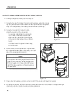
Figure 25.
MANUAL MODE COMPONENT REMOVAL
1. Install the proper Nozzle Assembly and Vacuum Cup onto the handpiece. Ensure that the PCB
assembly to be reworked and any replacement component have been properly prepared.
NOTE
Any required preheating operating should be completed before advancing
beyond this point.
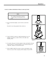
Figure 24.
2. Set unit POWER Switch (on power source rear panel) to the ON position.
Figure 23.
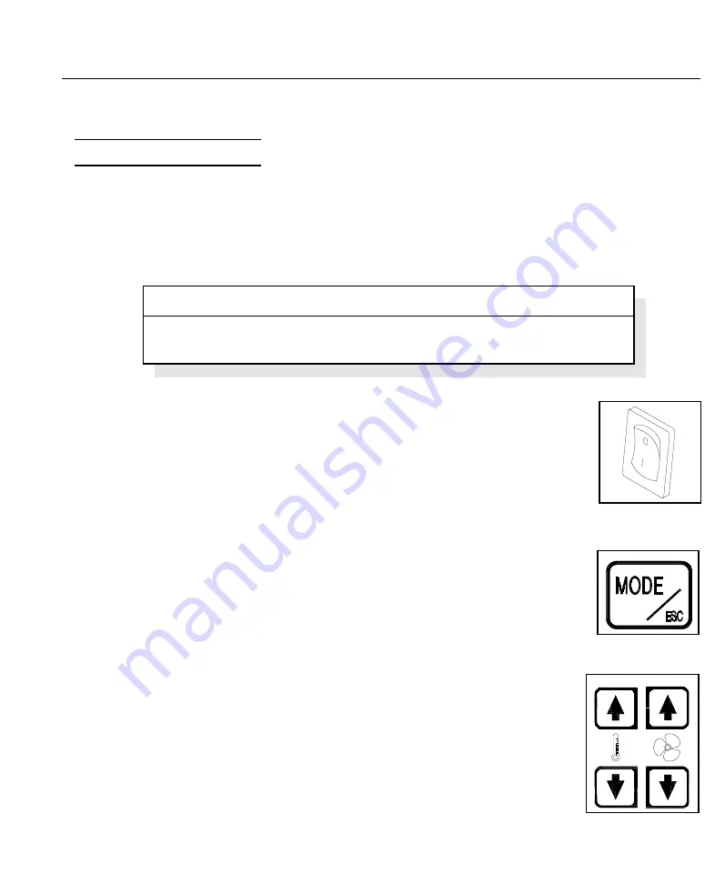
3. Press and release
MODE/ESC
Key as necessary until the
MANUAL
Mode Light
is illuminated.
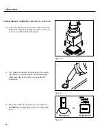
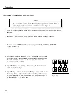
4. Adjust the Set Temp as desired using the Temperature Scroll Up and Down keys.
Press and hold the key; observe the Digital Readout as the Set Temperature
increases (or decreases) in 1° and then 10° increments as the key is held.
5. Adjust the Blower Speed (1-9) as desired using the Blower Speed Scroll Up and
Down keys.
33
Operation
Summary of Contents for TF 200
Page 2: ...MANUAL NO 5050 0420 REV C i ...
Page 26: ...21 Quick Start ...


