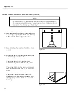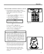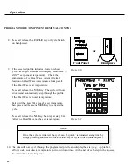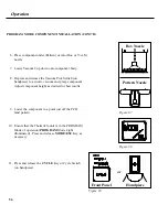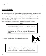
5. The Digital Readout will now display a “Profile =“
message with the current profile number. To select the
profile number you wish to use, do one of the
following:
NOTE
The Timed Mode Remove Light will now be
illuminated. A Save Current Profile? message may be
displayed on the Digital Readout if the last profile used
was not stored in memory. If so, press and release the
YES
or
NO
Key at this point. Use the YES Key if you
have entered a new profile or changed a profile you
wish to save. Additional message displays will step
you through the save process.
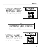
Figure 58.
Figure 59.
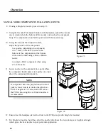
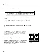
6. Adjust the vacuum cup to a point where the bottom
of the vacuum cup is flush with the bottom edge of
the nozzle using the Vacuum Pick Adjust Control.
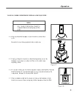
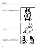
7. Lower the nozzle to a point .76-1.27mm (.030-
.050”) above the PCB when using Box or Pattern
nozzles. Lower the nozzle to contact a BGA
component.
a) Press and release the
STEP
Key to advance to
the next higher profile number.
b) Press and release the
BACK
Key to advance to
the next lower profile number.
NOTE
a & b will not work if "Profile = _ _".
or
a1)Press and release the
RECALL
Key.
b1)A “Recall - -” message will now be displayed.
c1)Enter the desired 2 digit profile number.
d1)Press and release the
ENTER
Key.
51
Operation
PROGRAM MODE COMPONENT REMOVAL (CONT'D)
Summary of Contents for TF 200
Page 2: ...MANUAL NO 5050 0420 REV C i ...
Page 26: ...21 Quick Start ...


