3
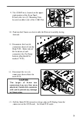
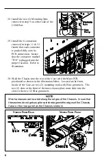
9. The COM Port is located on the upper
right portion of the Rear Panel.
Remove the two (2) Mounting Nuts
located on either side of the COM Port.
10. Position the Chassis as shown with the Blower Assembly facing
forward.
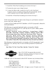
11. Disconnect the four (4)
connectors shown from the
Main PCB. Make note of
the location of each
connector (the Flo Pump
harness plug should be
marked "P10").
13. Pull the Main PCB forward to release pins on PCB plug from the
connector on the HV Board. Set Main PCB aside.
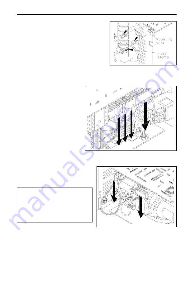
12. Disconnect the two (2)
connectors shown from the
main PCB.
CAUTION
The larger of these two
connectors has very fine wires
attached. Handle this connector
with care to prevent any damage
to these wires.


