6
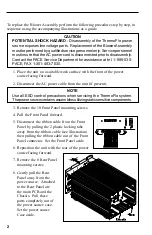
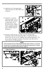
28. Install the two (2) Mounting Nuts
removed in step 9 on either side of the
COM Port.
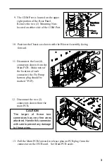
29. Install the 6 connectors
removed in steps 11 & 12.
Insure that each connector
is pushed fully onto its
PCB connection. Insure
that the connector marked
"P10" is plugged into the
proper location. Refer to
illustration.
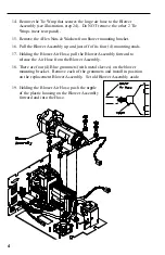
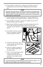
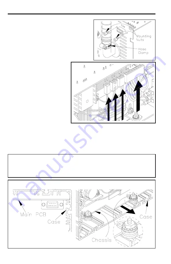
30. Slide the Chassis into the rear of the Case with the Main PCB
positioned as shown in the illustration below. Located at the front,
inside of the Case are two (2) mounting studs with Blue grommets. The
two (2) slots at the front of the inner chassis plate must slide into the
slots in the two (2) Blue grommets.
NOTE
Wire harnesses are located along the edges of the Chassis. Insure that
these wires do not get caught or pinched against the edges of the Chassis,
Case or the rear panel as the Chassis slides in.
V
IEWED
F
ROM
R
EAR
V
IEWED
F
ROM
F
RONT


