


©2010 PACE Inc., Annapolis Junction, Maryland All Rights Reserved
Page 5 of 11
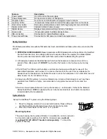
1. Mount the bracket in the desired location (fasteners not supplied).
2. Insert the 2 Mounting Screws (head first) into the power source mounting slots.
3. Place the washers over the screws.
4. Fit the power source between the bracket’s support arms and place the screws into the slots on
the support arms.
5. Place the nut on the screw and tighten by hand.
6. Angle the power source so the operator can see the front panel easily.
7. Tighten the nuts with a wrench or pliers.
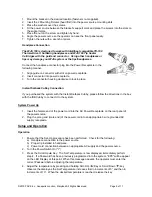
Handpiece Connection
The WJS 100 is designed to work with Intelliheat compatible TD-100
Thermo-Drive ® Soldering handpieces and WJS 100 Tip heater
Cartridges with the gold end connector. Using other handpieces or
tips may damage your WJS system or the tips/handpeices.
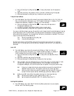
Connect the handpiece connector plug into the Power Receptacle in the
following manner.
1. Align guide on connector with slot on power receptacle.
2. Insert connector into power receptacle.
3. Turn the connector housing clockwise to lock in place.
Instant Setback Cubby Connection
If you purchased the system with the Instant Setback Cubby, please follow the directions in the box
with the ISB Cubby to connect it to the system.
System Power Up
1. Insert the female end of the power cord into the AC Power Receptacle on the rear panel of
the power source.
2. Plug the prong end (male end) of the power cord into an appropriate 3 wire grounded AC
supply receptacle.
Setup and Operation
Operation
1. Ensure that the Set-Up procedure has been performed. Check for the following:
a) Handpiece connection to the power source.
b) Proper tip installed in handpiece.
c) Power cord connection between an appropriate AC supply and the power source.
2. Turn the Power Switch On ("I").
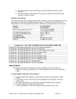
3. Press the Scroll Up
Key. The Set Temperature is now displayed, immediately perform
step 4. If a Password has been previously programmed into the system, "EP0" will be appear
on the LED Display at this point. When this message appears, the operator must enter the
correct Password before adjusting the temperature.
4. Adjust the temperature by pressing and holding Scroll Up
Key or Scroll Down
key.
Observe the display as the Set Temperature increases first in increments of 5° and then in
increments of 10°. When the desired temperature is reached, release the key.


