

©2010 PACE Inc., Annapolis Junction, Maryland All Rights Reserved
Page 6 of 11
NOTE:
The Set Temperature can only be adjusted within the defined temperature limits. If
the upper limit has been reached, the display will read “HiL”, if the Lo limit is reached, the
display will read “OFF”. Temperature limits can be adjusted in the Set-Up menu
5. An offset may be entered if using massive tips. To enter an offset, simply press the program
key while the system is in normal operation mode and enter the offset using the keypad. The
display will return to normal display mode in 5-7 seconds.
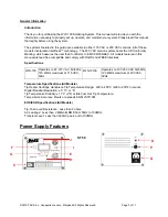
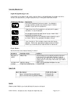
Digital Control LED Operation
The colored LED on the power source front panel indicates calibration status.
LED Full On Red –
A fault has occurred. Check handpiece and/or tip heater cartridge. Check
handpiece connection to front panel.
LED Full On Green –
Calibration of the TD-100 Thermo-Drive Soldering Handpiece is complete.
LED Full On Amber –
Calibration has not been completed.
LED Off -
Unit is in setback or Instant Set Back (ISB) Cubby is activated.
LED Display, Normal Operation
The LED Display provides a 3-digit display of temperature information. The LED Display will show:
1. A display of "888" on initial power up to ensure that all LEDs on the display are working.
2. A display of the software version of the installed microprocessor (e.g., "1-2") for 2 seconds on
initial power up after the "888" is displayed.
3. Actual tip temperature of the connected handpiece during normal operation.
4
The tip temperature displayed will flash when the system is in Temperature Setback.
5. The displayed temperature will decrease and stabilize at 177°C (350°F) when the system is
in Temperature Setback.
6. "OFF" with stable display when the Set Tip Temperature has been set to Off (below minimum
set tip temperature).
7. "OFF" with flashing display when the unit has entered Auto Off. Refer to the "Set-Up Mode"
portion of this manual.
8
Error messages ("OSE", "SSE" or "OCE") if a system fault is detected. Refer to the
"Corrective Maintenance" portion of this manual.
LED Display, Temperature Adjust Mode
The LED Display will show the following when adjusting the desired Set Tip Temperature.
1. The Set Tip Temperature.
2. "HiL" (High Temperature Limit) when adjusting the set tip temperature and the
maximum allowable temperature is exceeded. Refer to the "Set-Up Mode" portion of
this manual.
3. "OFF" (Low Temperature Limit) when adjusting the set tip temperature and the
minimum allowable temperature is exceeded. Refer to the "Set-Up Mode" portion of this
manual.
4. "EP" will be displayed if a Set Tip Temperature adjustment is attempted and a
Password has been stored in system memory. As the Password is entered, the zero
will increase by one as each key entry is made.
5. "no" will be displayed if the entered password does not match the stored Password.


