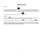
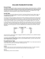
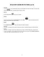
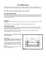
background image

  29

TROUBLESHOOTING


 CAUTION:  Unplug your treadmill before attempting any cleaning, maintenance, or service.


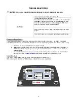
Is the magnetic key inserted into the control panel?


Is treadmill plugged into the wall outlet?


Check the household circuit breaker to see if it is tripped.   The treadmill 

will 

not operat

e if plugged into a GFCI (Ground Fault Current Interrupt) outlet.


Check the treadmill circuit breaker (See Figure 8, page 31).  If the circuit 

breaker is tripped, push reset button back in to reset. 


Make sure the wiring harness is plugged into the power supply (See Step 2, 

page 8). 


No Power 

Check both the black power cord and the black wiring harness for damage. 


Electronic Error Codes 

Your self-diagnostic PaceMaster treadmill has built in sensors that will determine the precise reason for a problem.  If the onboard 

computer detects a problem, an error code will be displayed. If an error code appears during operation of your treadmill, do the following: 


Make a note of the error code number (see next page for example). 


Obtain your serial number, located on the front of the treadmill approximately 10-12 inches to the left of the power cord.  


Write down which mode of operation you were using, the speed and incline that were set and if you were pressing any 
buttons at the time. 


Contact the PaceMaster dealer where you purchased your treadmill.  If you have moved or need the name of the local 
dealer, visit our website at


www.pacemaster.com 

and choose the dealer locater to find this information. 


Example Error Code 

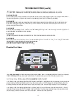
If the onboard computer detects a problem, an error code will be displayed. (Example - Err 149) 

“Err” 

will display in the Time Window

, “149” 

will display in Results Window (see example below). 

WARM UP

COOL DOWN

SELECT


Err 

149 

Summary of Contents for Bronze Basic

Page 1: ...PaceMaster Bronze Basic WARM UP COOL DOWN SELECT OWNER S MANUAL Manufactured by Aerobics Inc 34 Fairfield Place West Caldwell NJ 07006 973 276 9700 www pacemaster com Part TMP1626 Rev 11 16 09 ...

Page 2: ... 19 Warm Up and Cool Down 19 Quick Start 20 Timed Workout Manual 21 Programs 22 23 Program Specifications 24 EXCLUSIVE PACEMASTER FEATURES 25 26 Exercise Preview 25 Aerobic Points 25 Personal Electronic Trainer 25 26 CARE AND MAINTENANCE 27 Deck and Tread Belt Cleaning 27 Lubrication 27 Centering the Tread Belt 27 Cup Holder 28 TROUBLE SHOOTING 29 32 Electronic Error Codes 29 30 Noises 31 Hesitati...

Page 3: ...ndicates important safety warnings throughout the manual Failure to read and understand these warnings may result in personal injury or damage to your treadmill Tip indicates a useful suggestion when installing maintaining or using your treadmill Your PaceMaster treadmill is capable of varying your workout by changing speed incline and time It can also measure the effect of your workout in a numbe...

Page 4: ...tachments not recommended by Aerobics Inc Never operate your PaceMaster treadmill if it has a damaged cord or plug if it is not operating properly if it has been dropped or damaged or if it has been immersed in water Should any of these occur contact your authorized PaceMaster retailer or service center for examination or repair Keep the cord away from heated surfaces Never drop or insert any obje...

Page 5: ...t the contents of the package match the hardware legend included in the hardware package If any parts are missing contact the authorized PaceMaster retailer where you purchased your PaceMaster treadmill Hardware Kit Owners Manual Control Panel Front Control Panel Back Motor Cover Cup Holder w Foam Pad 2 pcs Panel Support Tube 2 pcs Treadmill Base Side Rail 2 pcs Upright Assembly Handle Bar ...

Page 6: ...conductor and a grounding plug The plug must be plugged into an appropriate outlet that is properly installed and grounded in accordance with all local codes and ordinances See example to the right WARNING Improper connection of the equipment grounding conductor can result in a risk of electrical shock Check with a qualified electrician or serviceman if you are in doubt as to whether the product i...

Page 7: ...the bottom of the upright line up with the holes in the frame Insert the 3 5 carriage bolts 3 through the upright and the frame Loosely install a 1 4 20 kep nut 4 to each carriage bolt to keep the upright in place Follow the same procedure for the other side of the upright Do not tighten any nuts until Step Ten 1 4 2 4 3 2 ...

Page 8: ...re harness 5 into the socket 6 on the power supply board Twist open the purse clip at 7a insert the wire harness 5 and secure the purse clip Confirm the wire harness is positioned as shown at point 5 above Follow the same procedure for purse clip 7b Step Three Route the wire harness 8 through the opening in the back of the control panel 9 then lower it on to the upright and let it rest as shown in...

Page 9: ... 3 hex bolt 13 and a 20 kep nut 14 loosely screw together the panel support tube 12 and the upright 2 See FIG B Follow the same procedure on the opposite side Make sure wire harness 8 is routed between bolts 10 and 13 See FIG B C Place spacer 15 in the upright on top of bolt 13 on both sides See FIG C Proceed to securely tighten all 4 bolts NOTE If spacer 15 is dropped into the upright 2 then upri...

Page 10: ...as shown below Pull the wire harness taut then apply tape 1 exactly as shown Repeat and apply tape 2 exactly as shown Harness must be flat against the side wall of the black plastic housing between tape 1 and tape 2 Plug the end of the wire harness into the connector on the circuit board All the slack in the wire harness should be near the connector 16 ...

Page 11: ...17 Start with the screw labeled 17 and proceed in a clockwise tightening sequence 17 Step Eight Insert side rail spacer 18 onto the black panel support tube 12 Slide side rail 19 over the spacer Repeat procedure on opposite side of the machine Note Make sure the siderail 19 slides all the way into the panel 19 18 12 17 ...

Page 12: ...be at the top facing the frame and finally through the frame 2 Install a 1 fender washer 22 and a 20 kep nut 4 to the bolt and hand tighten Install the other side rail following the same procedure Tighten both side rails with a 7 16 wrench Step Ten Tighten the 4 20 kep nuts 4 installed in step one These will secure the upright assembly 4 22 20 21 19 4 ...

Page 13: ...g scratched and reduce noise DO NOT THROW AWAY Step Twelve To install the motor cover stand in front of the treadmill Pick up the motor cover 24 so it is level Holding the motor cover level and waist high tilt it 45 degrees by lowering your left hand Then slide it between the handlebars and lower the motor cover until it is level Lower the cover all the way keeping it level Screw the two 8x1 2 bla...

Page 14: ...14 Assembly cont d Step Thirteen Assembly is complete please proceed to testing your treadmill on the next page ...

Page 15: ...nter your weight Step Four Set the workout speed by pressing the SPEED button until the SPEED display shows 2 5 mph Step Five Press the START button Within a few seconds the tread belt will begin to move The speed display will flash until the tread belt has reached the set speed Step Six After the treadmill has reached 2 5 mph observe the tread belt to make sure it is reasonably centered If the tr...

Page 16: ...ged During exercise an emergency stop can be made at any time by pulling on the cord to release the key from its slot CAUTION Using the key to stop the treadmill is an emergency procedure only To end your exercise routine normally press the STOP button or allow the timer to count down to zero Once the belt has come to a complete stop remove the MAGNETIC SAFETY KEY to turn off the treadmill When no...

Page 17: ... 11 PROGRAMS buttons In the WORKOUTS window press the desired Variable Intensity Workout profile to select that workout your selection is confirmed by the workout indicator light illuminating For details refer to the VARIABLE INTENSITY WORKOUTS section in this manual PROGRAM INTENSITY LEVEL TIMER buttons Has two functions 1 Use these buttons to set your workout time for both a TIMED WORKOUT and a ...

Page 18: ...ut the displayed Incline is the maximum incline that will be encountered during the selected workout and intensity level SPEED Max indicator When illuminated during selection of a Variable Intensity Workout the displayed speed is the maximum speed that will be encountered during the selected workout and intensity level WARM Up and COOL DOWN indicators Illuminated Warm Up or Cool Down indicators sh...

Page 19: ... the back and extremities and create a slight acceleration of the heart rate so that the body can move gradually into the higher heart rate of the aerobic phase The aerobic phase should be followed by a minimum 5 minute cool down in which you keep moving at a slower pace This allows your heart rate to gradually decline and your body to gently adjust to the end of a workout instead of abruptly stop...

Page 20: ...pressing the SPEED buttons Speed will adjust in 0 1 mph increments Add incline at any time during your workout by pressing the INCLINE buttons Elevation will adjust in 0 5 increments Add a 5 minute Cool Down to the end of your workout by pressing the WARM UP COOL DOWN button when you are ready TIP You can pause your workout at any time by pressing the PAUSE button To resume press the START button ...

Page 21: ... cool down to your workout press the WARM UP COOL DOWN button until the indicator light next to the desired mode is illuminated You will notice that your workout time will automatically increase by 5 minutes for each addition For details refer to the WARM UP AND COOL DOWN section in this manual Adjust incline by pressing the INCLINE buttons Elevation is adjusted in 0 5 increments Step Six Press ST...

Page 22: ... Three Step Two You will see the number 150 in the INCLINE display window and the SET WEIGHT indicator light will be blinking Set your weight using the incline buttons The default weight set at the factory is 150 lbs Step Three Press the PAUSE ENTER button to enter your weight Step Four In the PROGRAMS window press the PROGRAM button of the course you desire The indicator light next to the chosen ...

Page 23: ...uttons Step Eight Press the START button and your PaceMaster will gradually accelerate Your workout will end when the timer has counted down to zero or the STOP button is pressed Total time calories Aerobic Points and distance will be displayed TIP You can pause your workout at any time by pressing the PAUSE button To resume press the START button If a problem should occur your PaceMaster can be s...

Page 24: ...4 2 6 0 0 6 0 2 2 0 3 2 0 0 6 0 3 2 6 3 8 0 0 6 0 4 3 2 4 4 0 0 6 0 5 3 8 5 0 0 0 6 0 6 4 4 5 6 0 0 6 0 7 5 0 6 2 0 0 6 0 8 5 6 6 8 0 0 6 0 9 6 2 7 4 0 0 6 0 INTERVAL TRAINER Level Speed Incline Min Max Min Max 1 1 6 2 8 0 0 6 0 2 2 2 3 4 0 0 6 0 3 2 8 4 0 0 0 6 0 4 3 4 4 6 0 0 6 0 5 4 0 5 2 0 0 6 0 6 4 6 5 8 0 0 6 0 7 5 2 6 4 0 0 6 0 8 5 8 7 0 0 0 6 0 9 6 4 7 6 0 0 6 0 GLUTE TONER Main Workout Wa...

Page 25: ...rogram For Total Well Being The main idea of this system is that in order to stay in good shape and move toward a goal of total well being a person must earn a certain number of points each week by doing a certain amount of aerobic exercise His research has determined that a man should work up to a minimum of 32 points per week and a woman should work up to a minimum of 27 points per week The numb...

Page 26: ...e appears you may also add a warm up and or cool down Step Six Press the SELECT Preview SELECT button until the Aerobic Points indicator is illuminated Step Seven Enter speed You will begin to see the number of Aerobic points you will earn in the RESULTS display as you increase the speed Step Five Enter Incline You will begin to see the number of Aerobic points you will earn in the RESULTS display...

Page 27: ... applying a coat of automotive wax to them will help prevent rusting Centering the Tread Belt To improve belt life the belt should be reasonably centered To center the belt walk on the treadmill at 2 5 mph for a few minutes Determine whether the belt drifts too far to the left or right side If adjustments are required stop the treadmill and follow the steps listed below Never make adjustments whil...

Page 28: ... snapped in place If not remove cup holder and rotate 180 degrees then reinstall Removal Simply tap the bottom the of cup holder with the palm of your hand until it is released from the snaps Pull up until it completely clears the control panel Cleaning To safely clean your cup holder simply hand wash with dish soap or placed in a dishwasher TOP RACK ONLY The black foam pad can be rinsed off and l...

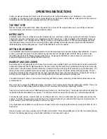
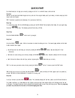
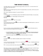
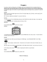
Page 29: ...e precise reason for a problem If the onboard computer detects a problem an error code will be displayed If an error code appears during operation of your treadmill do the following Make a note of the error code number see next page for example Obtain your serial number located on the front of the treadmill approximately 10 12 inches to the left of the power cord Write down which mode of operation...

Page 30: ...from the wall outlet for 10 seconds and then check the items listed below Check the drive motor wire connection to the power supply Check the ceramic fuse 20 Amp 250 V on the power supply Elevation Error Codes Err in the Incline Display indicates a problem with the elevation system Note The treadmill will still function with the Err displayed in the incline Display but the elevation system will no...

Page 31: ... indicates slippage of either the tread belt the belt you walk on or the drive belt the belt connecting the drive roller to the motor To determine which of these belts is slipping first adjust the drive belt tension and test to see if the slippage stops If the hesitation is not corrected than the tread belt tension needs adjustment CAUTION Unplug your treadmill before attempting any cleaning or ma...

Page 32: ...ment screw 1 1 2 turns and there is still hesitation slippage contact your authorized PaceMaster dealer Tightening the drive belt adjustment screw more than 1 1 2 turns can result in bearing damage to the motor and or drive roller Tread Belt Tension Adjustment This step requires the 3 16 T handle allen wrench that came with your treadmill Step One Locate the two tread belt adjustment screws 3 4 in...

Page 33: ... the total hours and miles on my treadmill A Insert the magnetic safety key when the set weight indicator begins to flash press and hold the PROGRAM INTENSITY LEVEL button the total time and mileage will appear in their respective windows and the power supply software version will appear in the INCLINE Q Can I eliminate warm up and or cool down from a Variable Intensity Workout A Yes If you wish t...

Page 34: ...ce free custom designed medium density fiberboard Rollers 2 5 OD precision machined steel with permanently lubricated sealed bearings Shock Absorption System Tri Flex Low Impact Cushioning System Speed Range 0 5 to 11 0 mph adjustable in 0 1 mph increments Elevation Range 0 to 15 grade adjustable in 0 5 increments Workout Programs Quick Start Manual and 4 Variable Intensity Programs each with 9 le...

Reviews: