background image

VT_user manual-eng / rev.04                                                                                                                                                                  Page 2 – April 2015 


VT_user manual-eng 


Chilled water buffer vessels 

V

V

V

T

T

T

-

-

-

G

G

G


/

/

/


V

V

V

T

T

T

-

-

-

Z

Z

Z


/

/

/


V

V

V

T

T

T

-

-

-

X

X

X


/

/

/


V

V

V

T

T

T

S

S

S


/

/

/


V

V

V

T

T

T

P

P

P


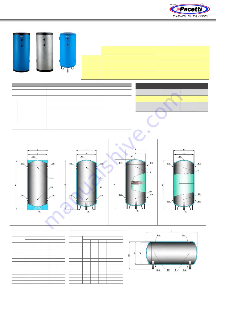
Open buffer vessels 

VT-G / VT-Z / VT-X


Buffer vessels with perforated central 

divider plate / multiple flow dividers 

VT-S / VT-P


Vessel 

material 


VT-G / VT-Z 

 Mild carbon steel 


VT-X 

 Stainless steel 316 

VTS / VTP 

 Mild carbon steel 

Inside 

coating 


VT-G 

 None 


VT-Z 

 Dip hot galvanizing 


VT-X 

 Pickling 

VTS / VTP 

 None 

Outside 

coating 


VT-G 

 Anti rust primer 


VT-Z 

 Dip hot galvanizing 


VT-X 

 Pickling 

VTS / VTP 

 Anti rust primer 


100 

÷


1000 l 

PVC


100 

÷


1000 l 

Aluminium


1500 

÷


5000 l 

PVC


Characteristics 

STANDARD SUPPLY 

UPON REQUEST 

Capacity 

100 ÷ 5000 litre 

> 5000 litre 

Version 

Vertical 

Horizontal 

(1)


Low / extra low 

(2)


Connections 

Threaded type 

Flanged type 

In

su

la

ti

o

n


VERTICAL 

version 

VT-G / VT-Z: 


30 mm hard foam PU 

 100÷1000 l 


20 mm closed cell elastomer 

 1500÷5000 l 


VT-S / VT-P / VT-X: 


20 mm closed cell elastomer 

 300÷5000 l 


HORIZONTAL version  

and  

OUT OF STANDARD 

VT-G / VT-Z / VT-X: 


20 mm closed cell elastomer 

 100÷5000 l 


Cladding 


Coloured PVC with zipper fastening 


Embossed aluminium 0.4 mm 


VESSELS STANDARD WORKING 

CONDITIONS 

(3)


Model 

Max 

temperature


Max 

pressure 

Mild steel  

vessels 

-10°C/+50°C 

≤ 1000 l 

8 bar


≥ 1500 l


6 bar 

Stainless steel 

vessels 

-10°C/+50°C 

≤ 300 l 

10 bar


500÷2500 l


8 bar 

≥ 3000 l


6 bar 


Connections 

E-U  Inlet / Outlet 

T  Thermometer 

SD  Sensor 

SF  Vent 

S  Drain 


D ime nsi ons  


VERTICAL OPEN BUFFER VESSELS


VERTICAL BUFFER VESSELS  

WITH PERFRORATED CENTRAL 

DIVIDER PLATE


VERTICAL BUFFER VESSELS  

WITH MULTIPLE  

FLOW DIVIDERS 


VT-G / VT-Z / VT-X 

30 mm hard foam PU 

insulation 

100÷1000 l


VT-G / VT-Z / VT-X 

20 mm closed cell 

elastomer insulation 

1500÷5000 l


VT-S 

20 mm closed cell 

elastomer insulation 

300÷2000 l


VT-P 

20 mm closed cell 

elastomer insulation 

300÷2000 l


Mild steel vessels 

VT-G / VT-Z / VTS / VTP 

Capacity 

Dimensions (±5%) * 

H1 

Litre 

mm 

mm 

mm 

mm 

mm 

100 

460 

400  1070  940 

590 

200 

510 

450  1460  1340  640 

300 

610 

550  1500  1390  800 

500 

710 

650  1790  1690  890 

800 

860 

800  1870  1770  1040 

1000 

860 

800  2120  2020  1040 

1500 

1000  950  2430  2290  1180 

2000 

1150  1100  2480  2360  1330 

2500 

1250  1200  2560  2430  1480 

3000 

1300  1250  2760  2640  1540 

4000 

1450  1400  2840  2730  1680 

5000 

1650  1600  2930  2790  1870 


Stainless steel vessels 

VT-X 

Capacity 

Dimensions (±5%) * 

H1 

Litre 

mm 

mm 

mm 

mm 

mm 

100 

460 

400  1090  940 

610 

200 

510 

450  1480  1340  660 

300 

610 

550  1520  1390  800 

500 

710 

650  1810  1690  890 

800 

860 

800  1890  1790  1040 

1000 

860 

800  2140  2040  1040 

1500 

1050  1000  2180  2050  1240 

2000 

1250  1200  2250  2140  1430 

2500 

1250  1200  2580  2450  1480 

3000 

1300  1250  2780  2660  1540 

4000 

1450  1400  2860  2750  1680 

5000 

1650  1600  2950  2810  1870 


HORIZONTAL OPEN BUFFER VESSELS


VT-G / VT-Z / VT-X 

20 mm closed cell 

elastomer insulation 

100÷5000 l 

* Dimensions may change in case of bespoke solutions 

Cooke Industries - Phone: +64-9-579 2185  Fax: +64-9-579 2181  Email: sales@cookeindustries.co.nz  Web: www.cookeindustries.co.nz

Summary of Contents for VT-G

Page 1: ... T T G G G V V VT T T Z Z Z V V VT T T X X X V V VT T TS S S V V VT T TP P P Chilled water buffer vessels USER AND MAINTENANCE MANUAL Cooke Industries Phone 64 9 579 2185 Fax 64 9 579 2181 Email sales cookeindustries co nz Web www cookeindustries co nz ...

Page 2: ...Outlet T Thermometer SD Sensor SF Vent S Drain Dimensions VERTICAL OPEN BUFFER VESSELS VERTICAL BUFFER VESSELS WITH PERFRORATED CENTRAL DIVIDER PLATE VERTICAL BUFFER VESSELS WITH MULTIPLE FLOW DIVIDERS VT G VT Z VT X 30 mm hard foam PU insulation 100 1000 l VT G VT Z VT X 20 mm closed cell elastomer insulation 1500 5000 l VT S 20 mm closed cell elastomer insulation 300 2000 l VT P 20 mm closed cel...

Page 3: ...move contaminants Thermal insulation against condensation HARD FOAM POLYURETHANE Hard foam polyurethane injected Made of hard foam polyurethane 30mm thick density of 40 to 42 kg m3 average conductivity of 0 024 W mK CFC and HCFC free Closed cell elastomer foam Made of closed cell elastomer foam sheets 20mm thick density of 30 kg m3 average conductivity of 0 034 W mK CFC and HCFC free Insulation Ta...

Page 4: ...PLE Closed circuit plant with chilled water storage tank installed on return Description A1 Heat pump air conditioner split system A2 Heat pump air conditioner monoblock B External unit C Fan coil unit D Pump E Expansion vessel F Storage tank Installation in a double circuit plant Cooke Industries Phone 64 9 579 2185 Fax 64 9 579 2181 Email sales cookeindustries co nz Web www cookeindustries co nz...

Page 5: ... in order to perform future maintenance verify that the room where the tank is placed has openings of a size to allow the free passage of the vessel in case it s necessary to bring it out in order to avoid any demolition 1 3 START The connection diagram shown in this document is purely indicative and not binding it s up to the designer of the system to give the best connection scheme for the requi...

Page 6: ...lcohol is not recommended 3 DEFECTS AND FAILURES PROBLEM CAUSE SOLUTION Excessive pressure inside the tank Expansion vessel lack or malfunctioning The pressure of the expansion vessel air cushion is not enough Verify that the system is equipped with an expansion vessel If the expansion vessel is present check that the precharge pressure is set correctly it must be restored to the initial valued sl...

Reviews: