Page 13
Rev 508jf
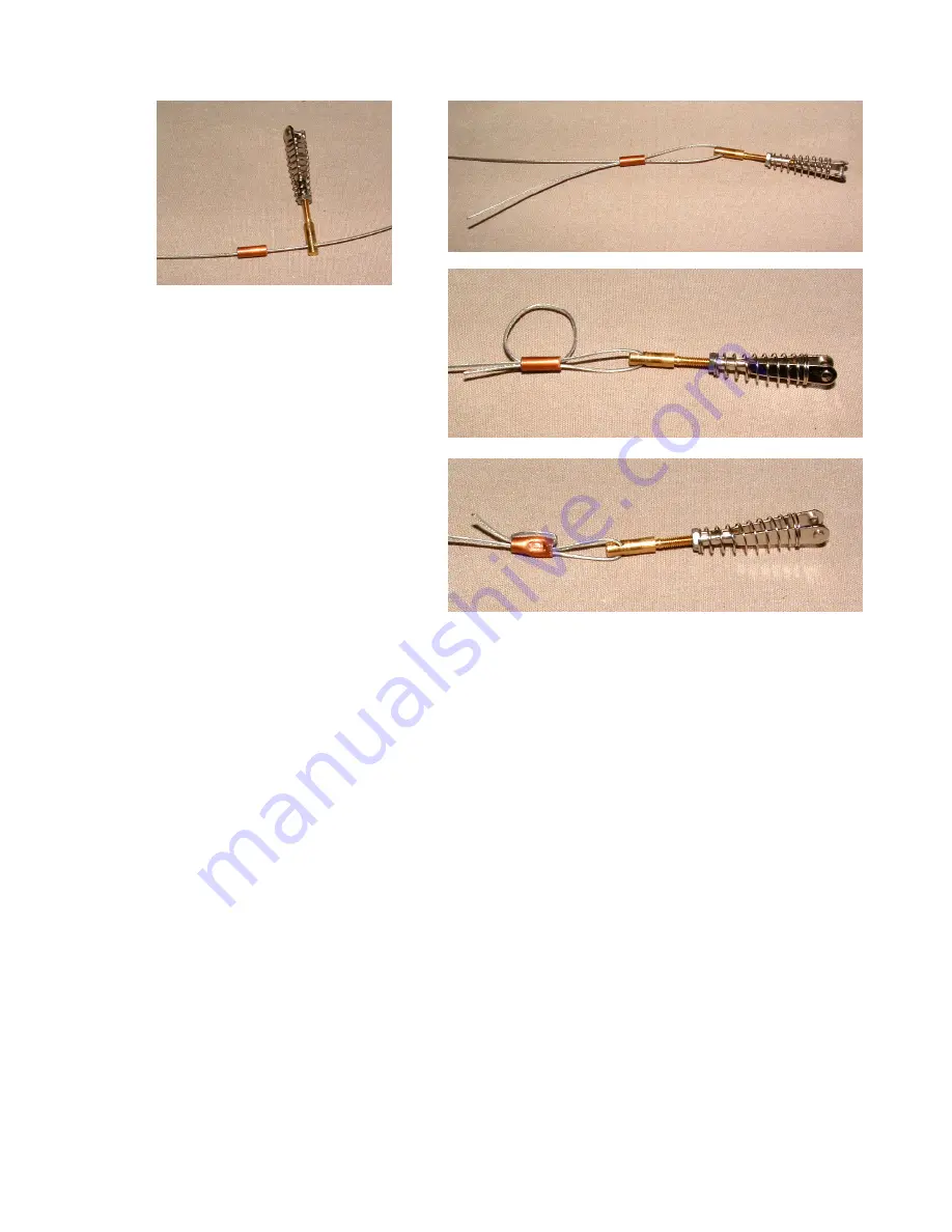
Pass one end of the cable through a
crimp tube and through the hole in the
threaded adapter.
Loop the cable back through the crimp
tube in the other direction, leaving
about 3” of cable past the tube.
Now loop the cable over the tube and
pass it through the tube a third time
going away from the clevis.
Pull the cable tight and squeeze the
crimp tube with a crimping tool or a
pair of pliers. Clip off any excess
cable. We like to put a drop of thin CA on each end of the crimp tube for added insurance.
Locate the cable exit in each side of the fuselage. Attach the finished end of the cables to the
outer holes in the rudder horns and feed the cables through the exits and forward in the fuselage.
(This is easy to do if you stand the fuselage on its nose.)
ATTACH THE CABLES TO THE SERVO. Attach the remaining loose clevis/adapter
assemblies to the outer holes of the servo arm. Center the rudder servo with your transmitter. Do
not cross the cables inside the fuselage. Clamp the rudder in a centered position. Stretch one
cable across the hole in the brass clevis adapter on that side and make a mark on the cable. Now
make a sharp 90-degree bend in the cable at the mark.
Remove the clevis assembly from the servo arm. Slide a crimp tube onto the cable, past the bend.
Now slip the cable through the hole in the clevis adapter up to the bend, then bend the cable back
on itself so that it makes a “U” through the adapter.
Pass the free end of the cable through the crimp tube, then loop the cable back toward the clevis
and pass it through the tube again. Pull the cable tight, squeeze the tube and clip off the excess.
Do the same with the other cable.
ADJUST THE CABLES. Reattach the clevises to the servo arm and use the clevis adapters on
both ends of the cables to adjust the centering of the rudder and the tension of the cables. The
cables should be tight enough to emit a base note when you “strum” them.


