background image

PC-10053 

13

F

If the 

fi

 nal loca

ti

 on for your gazebo is a so

ft

  surface, you may secure it by 

driving the provided stakes (part F) through holes at the bo

tt

 om of each 

gazebo leg panel (parts A and B)

NOTE:


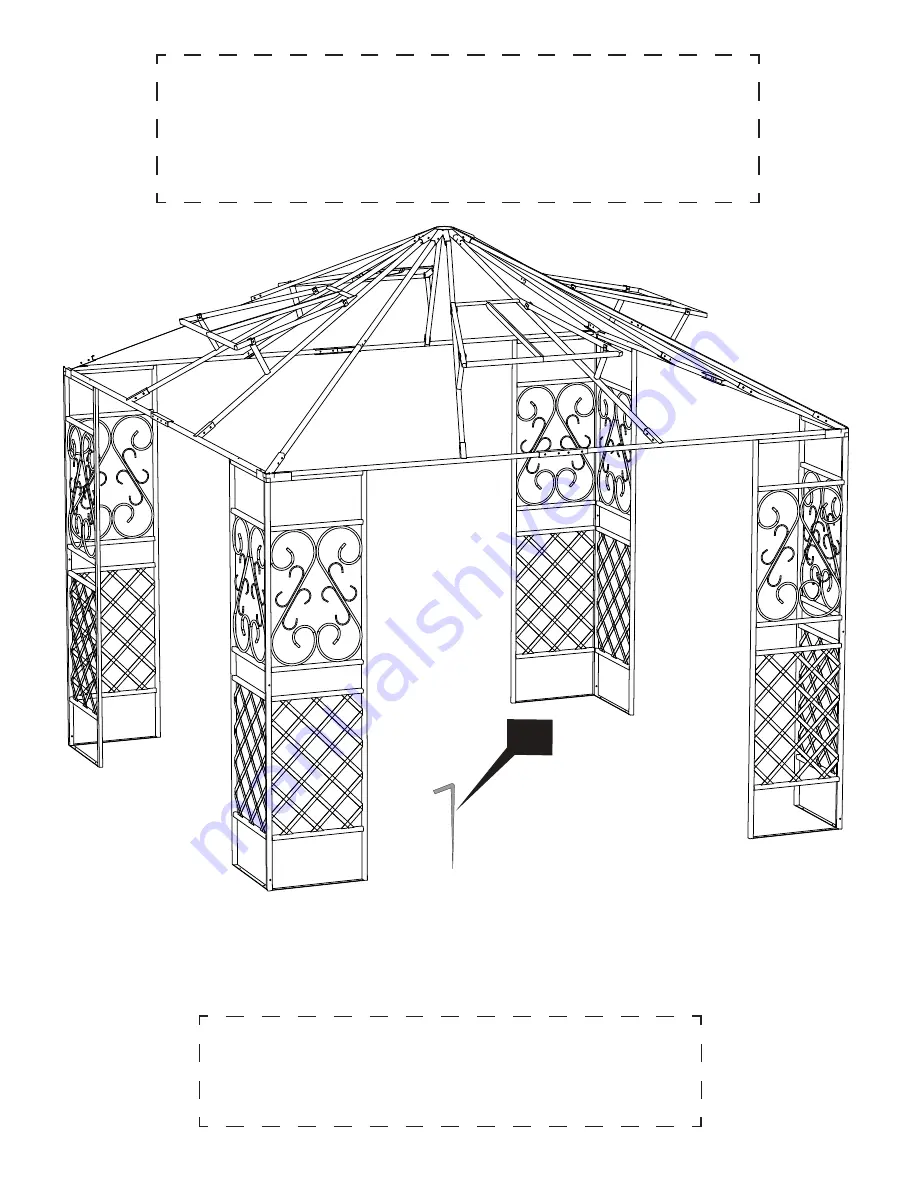
Your gazebo should now resemble the image below.  

Please check to make sure all parts are in their respec

ti

 ve 

loca

ti

 ons.

NOTE:


 Lawn stakes for use only on natural surfaces (grass 

or dirt) and not meant to permanently secure gazebo to the 
ground in high winds.

Summary of Contents for Palladian Gazebo PC-10053

Page 1: ...ns and Owner s Manual Item Numbers PC 10053 and PC 30053 Actual canopy top color and panel design may vary available in taupe and chocolate Palladian Gazebo Agora Outdoor Living TM Design and Manufact...

Page 2: ...tools a ladder and an adjustable wrench You may also need these additiontal tools optional work gloves waterproofing spray Prepare the work area General Notes Pre Assembly Steps Thank you for choosing...

Page 3: ...PC 10053 3 Parts Identification B C D H E A G O Note Not drawn to Scale x 4 x 4 x 4 x 1 x 4 x 4 x 8 x 4...

Page 4: ...ly Bug Screen Sunshade K x 4 x 16 x 4 I Important For missing or defective parts Do NOT return to the place of purchase Call our toll free number below or visit www pacificcurrents com Please have you...

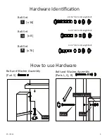
Page 5: ...1 16 52 mm Length Bolt Bolt Set L x 76 x 8 1 1 4 32 mm Length Bolt 1 1 4 42 mm Length Bolt Bolt Set Bolt Set R Q How to use Hardware Bolt and Washer Assembly Part S Bolt and Washer Assembly Parts L Q...

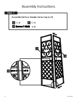
Page 6: ...6 PC 10053 Assembly Instructions Step 1 Assemble the Four Gazebo Corner Legs x 4 x 8 x 4 x 4 Q A B Q B A...

Page 7: ...PC 10053 7 Step 2 Assemble the Four Cross Bar Connectors x 4 x 16 R x 4 x 4 x 4 G H E R H E G...

Page 8: ...nt place all the gazebo legs in an upright position over the final location you have chosen for the gazebo and gather the remaining assembled pieces from steps 2 4 Remember please do not tighten any o...

Page 9: ...PC 10053 9 x 4 x 4 x 4 A B G H C A B G H A B Step 5 Attach Gazebo Legs to Cross Bar Connectors x 8 L L C C...

Page 10: ...10 PC 10053 Step 6 Attach Canopy Corner Bars J K to Top Connector D R R R x 12 D J K J K J K J K x 1 x 4 D J K...

Page 11: ...PC 10053 11 R R Step 7 Attach the center support bars to the canopy frame x 8 R x 24 D O O x 8 O...

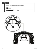
Page 12: ...12 PC 10053 Step 8 Attach the canopy vents to roof frame R x 16 I R R R R x 4 I...

Page 13: ...through holes at the bottom of each gazebo leg panel parts A and B NOTE Your gazebo should now resemble the image below Please check to make sure all parts are in their respective locations NOTE Lawn...

Page 14: ...old Separately NOTE Carefully pull the canvas top over the gazebo roof frame and slide the vent bars into each respective vent opening in the canvas The fit will be very snug You may need to repositio...

Page 15: ...w the gazebo to remain very stable across a range of weather conditions The four vents in the canopy top help to allow low to medium winds to pass through the covering However if you install the gazeb...

Page 16: ...it in a location that is dry and free of moisture 1 Year Limited Warranty Purchaser assumes all risk in the assembly and use of this unit All components carry a one year limited warranty from date of...

Reviews: