background image

9

ALT5.CPINSB 080515-24

©PACIFIC ENERGY FIREPLACE 
PRODUCTS LTD.

O/A Cover Screw

O/A Cover

Fig. # 5

Fig. # 6

Fig. # 7

Combustion Air

Consult local building codes regarding combustion air supply. 
Intake or combustion air can be supplied to the Insert in one 
of two ways:

1)  Outside air (O/A) supply:  Remove cover from ash clean 

out in existing fi replace. Place a rodent screen in place 
of the cover. Install the Insert as described in the installa-
tion section, making sure not to cover the opening of the 
air inlet. When installation is complete, seal surround to 
fi replace and anywhere else air may enter. This will ensure 
combustion air is drawn from outside the house and into 
the 9” x 2” intake at the lower rear of the appliance.

2)  Room air supply:  Install the Insert as described in the 

installation section. When the installation is complete, 
do not seal surround to fi replace. This will allow enough 
combustion air to enter the fi replace cavity and the Insert. 
The knockouts in the casing sides and the O/A cover can 
be removed to supplement air supply (Fig.6 & 7). Once 
removed, combustion air is drawn from the room into the 
lower front of the Insert.

Removal:  The O/A cover should be removed prior to installa-
tion. For better access, tip the Insert onto its back.

1.  Using a 5/16” wrench, remove the screw securing the O/A 

cover to the fi rebox (Fig. #5 & 6).

This unit is not designed to be operated with the fi ring door 
open. In addition to the obvious hazard of sparks landing on 
combustibles, an open fi re door will cause the heater to draw 
air from the living space and possibly cause suffocation.
The living space around the heater must be well ventilated 
with good air circulation. Anything that may cause a negative 
pressure can cause gases or fumes to be pulled into the liv-
ing area.

Remove Knockout

Summary of Contents for Alderlea T5 Classic Insert

Page 1: ...ED and LISTED to ULC S628 UL 1482 Meets the U S Environmental Protection Agency s May 2015 Particulate Emission Standards SERIAL SAFETY NOTICE If this stove is not properly installed a house fire may...

Page 2: ...1 Warranty Information 22 Label 23 PLEASE SAVE THESE INSTRUCTIONS This manual describes the installation and operation of theAlderlea T5 INSERT wood heater This heater meets the 2015 U S Environmental...

Page 3: ...t restrictions and installation inspection require ments in your area Clearances Masonry or Factory Built Fireplace Theminimumrequiredclearancestosurroundingcombustible materialswheninstalledintoamaso...

Page 4: ...Top baffle board blanket Baffle Top heat shield and mounting bolt Baffle Gasket Brick Rails Manifold Some warping of the baffle is normal up to 1 4 or 65cm Replace if the baffle has permanent warping...

Page 5: ...ace opening may be flush to an adjacent combustible floor Ember protection Combustible floor in front of the fireplace insert must be protected from hot embers by non combustible material extend ing 1...

Page 6: ...IFIC ENERGY FIREPLACE PRODUCTS LTD 29 3 8 42 1 2 30 3 8 42 1 2 33 1 8 34 1 8 9 1 2 33 5 8 23 7 8 10 5 8 17 5 8 20 7 8 17 5 8 28 3 8 21 1 2 WITH REGULAR SURROUND WITH OVERSIZED SURROUND ALT5 INSERT ALT...

Page 7: ...in use for some time have chimney swept The existing fireplace damper is to be locked open or removed completely WARNING Do not remove bricks or mortar from your existing fireplace Exception Masonry...

Page 8: ...r area and into the first chimney flue tile Seal around pipe Note A clean out door may be required under local codes whenadirectflueconnectionisused Consultlocalcodes 3 To mount optional rear leveling...

Page 9: ...tion When the installation is complete do not seal surround to fireplace This will allow enough combustion air to enter the fireplace cavity and the Insert The knockouts in the casing sides and the O...

Page 10: ...Fig 10 Use the bolts and washers in the mounting hardware kit found with the Surround Top Fig 10 5 Lay Surround sides flat on floor and align with Surround Top H Square the surround by aligning edges...

Page 11: ...ecuring the fan bracket to the stove using a 7 16 socket or wrench Reverse steps 1 2 to install new fan Fig 17 7 Install fan shield as shown in Fig 13 Be sure to place the air inlet opening against th...

Page 12: ...nd side If required it can be relocated to the left side by following the instructions below To make this as easy as possible it is suggested that this be done prior to fitting the surround and instal...

Page 13: ...Wire placement is important to prevent damage to wires 7 Remove the control assembly from the ashlip bracket on the right hand side Flip it over and reattach on the left hand side of the ashlip Fig 2...

Page 14: ...waste of fuel Too slow a burn contributes to creosote buildup and lowers combustion efficiency Lighting a Fire WARNING Never use chemicals or any other volatile liquid to start a fire 1 Adjust air co...

Page 15: ...setting other than for starting or preheating fresh fuel loads DO NOT OVERFIRE THIS HEATER Attempts to achieve heatoutputratesthatexceedheaterdesignspecifications canresultinpermanentdamagetotheheater...

Page 16: ...C22 1 Canadian Electrical Code and in the USA withtheNationalElectricalCode ANSI NFPA70 latestedition Chimney Smoke and Creosote Formation When wood is burned slowly it produces tar and other or ganic...

Page 17: ...ler The size required is 11 3 8 x 17 1 4 x 5 mm Ceramic glass must be used Do not substitute with any other type To remove broken glass undo the four retaining screws and remove the clamps noting posi...

Page 18: ...el ALT5 P50274723BK Ashlip Assy Majolica Brown Enamel ALT5 P50374723BN Ashlip Assy Antique White Enamel ALT5 P50374723AW Replacement Parts WHEN ORDERING INCLUDE PART NUMBER WITH DESCRIPTION 2 3 4 1 5...

Page 19: ...igh mass weight acts as a heat storage and the thermalinsulationkeepsthecombustionzonehot Active flamingtakesplaceduringthefirstpartoftheburn During this stage heat is stored in the mass of the unit a...

Page 20: ...ee 1 2 and 3 above 2 Door Gasket leakage Replace gasket Check latch Low Heat Output 1 Wood is wet Use dry wood 2 Fire too small Build a larger fire 3 Area too large 4 Poor insulation or open concrete...

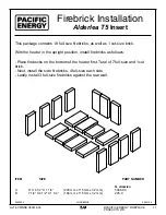
Page 21: ...a T5 Insert Firebrick Installation This package contains 18 full size firebricks as well as 1 cut size brick With the heater in the upright position install firebricks as follows Place firebricks on t...

Page 22: ...ectly at installation Any part that shows in our judgment evidence of defect shall be repaired replaced or refunded at Pacific Energy s option The defective part may be required to be returned to Paci...

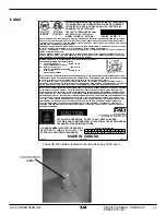
Page 23: ...UENTLY UNDER CER TAIN CONDITIONS OF USE CREOSOTE BUILDUP MAY OCCUR RAPIDLY MADE IN CANADA F M A M J J A S O N D 2010 2011 2012 2013 2014 2015 U S ENVIRONMENTALPROTECTIONAGENCY CERTIFIED TO COMPLY WITH...

Page 24: ...PACIFIC ENERGY FIREPLACE PRODUCTS LTD PACIFIC ENERGY FIREPLACE PRODUCTS LTD www pacificenergy net Technical Support 1 250 748 1184 2975 Allenby Rd Duncan B C V9L 6V8 Printed in Canada...

Reviews: