10
Fig. # 9
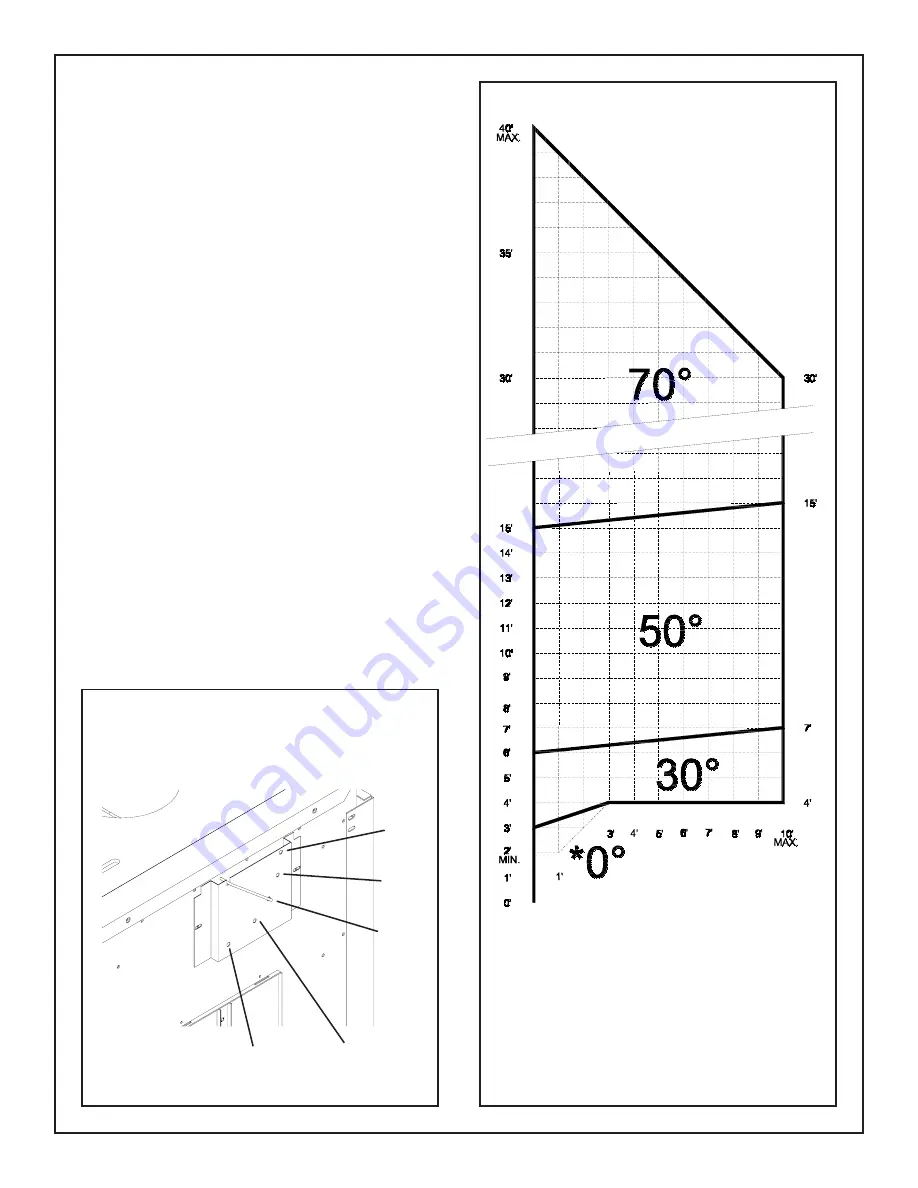
VENT RESTRICTOR
ADJUSTMENT
A vent restrictor damper is built into the appliance to adjust the
flow rate of exhaust gases. This ensures proper flames for the
wide variety of vent configurations.
Refer to the chart for the correct damper angle for the amount
of vent in your installation. Adjust the restrictor damper control
on the back of the unit by moving the control rod to the
appropriate index hole. Restrictor positions are based upon
lab tests. The ideal position may vary slightly with installation.
If necessary, adjust damper position as follows:
Damper position correction:
The damper position is correct if the rear right flame has the
following characteristics:
-
flame has yellow colour and some movement
-
flame is vertical
Damper has too much angle if the rear right flame has the
following characteristics:
-
flame is pale, blue, lifting, clear, or non existent
-
flame has no movement
Damper has too little angle if the rear right flame has the
following characteristics:
-
flame is bent forward
-
flame has excessive movement
90°
70°
50°
30°
0°
Fig. # 8
For reduced BTU input rate
of 25,000 NG, use restrictor
position of 30°
*
WALL AND ROOF
TERMINATION
RESTRICTOR
POSITION
RESTRICTOR POSITION
(shown with cover removed)


