background image

12

FUSION_D1

010604-16

Optional Blower

The optional blower kit (kit #WODC.BLOW) is equipped with
a three prong power cord and may be installed at any time.
Follow installation instructions supplied with the kit. Route
power supply cord away from heater.

Electrical rating:  115 volts A.C.-1.02 amps.
Fan output rating:  125 CFM
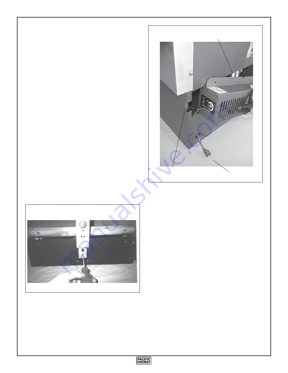
Blower Installation

1. Loosen the 2 screws at the center of the blower.
2. Install the temperature snap-switch assembly onto the

blower by placing the bracket over the screws.

3. Tighten the screws.
4. Ensure that the two wires are connected to the temperature

snap-switch.

5. Bend over the blower clearance tab and shown in the

picture.

6. Feed the power cord into the pedestal base and out through

the round hole near the bottom.

7. Slide the temperature snap-switch assembly up into the

space between the rear shield and the firebox, ensuring that
the temperature snap-switch contacts the firebox.

8. Install the two screws through the flange of the blower into

the rear shield.

9. Plug the power supply cord in and check blower operation.

Power Cord

Clearance

Tab

Temperature

Switch

Blower Operation

Proper blower speed matched with air control setting will
ensure peak performance from your stove. Operate as follows:

- Air control set to low (right-most position), operate
blower speed control on "Low".
- Air control set between low and high, operate blower
speed control at desired setting.

Automatic:

  To operate the blower automatically, set the

rocker switch on the side of the fan housing to "Auto" and set
the speed control to desired setting. This will allow the fan to
turn on as the stove heats up to operating temperature. It will
also shut the blower off after the fire has gone out and the unit
cooled to below a useful heat output range.

Manual:

  To manually operate the blower, set the rocker

switch to "Man" and set the speed control to desired setting.
This will bypass the sensing device and allow full control of the
blower.
Switching from "Auto" to "Man" or selecting speed may be
done anytime.

FIG. #5

FIG. #6

Summary of Contents for Fusion

Page 1: ...TION OPERATION GUIDE Design D Model FUSION PLEASE SAVE THESE INSTRUCTIONS SAFETY NOTICE Ifthisstoveisnotproperlyinstalled a house fire may result For your safety follow the installation instructions C...

Page 2: ...on 8 Clearances 8 Chimney and Connector 8 Double Wall Connector 8 Single Wall Connector 8 Procedure 8 Floor Protector 9 Combustion Air 9 Operation 10 Wood Selection 10 How to Test Your Wood 10 Lightin...

Page 3: ...nwoodandtoo slow a burning rate This heavy deposit is building up at least as quickly in the chimney WARNING ONLY USE MATERIALS SUPPLIED BY MANUFACTURER WHEN DOING MAINTE NANCE OR REPLACEMENTS 4 DOOR...

Page 4: ...ust be lived with Regular inspection and cleaning is the solution The use of dry seasoned wood and ample com bustion air will help to minimize the buildup Chimney Fires The result of excessive creosot...

Page 5: ...9 8 1 4 8 1 4 4 1 4 4 1 4 18 22 11 1 4 11 1 4 25 22 1 4 36 1 4 23 1 2 26 3 4 8 3 8 33 1 2 Minimum Clearance to Combustibles FIG 1 Double Wall Connector Residential Single Wall Connector Residential Al...

Page 6: ...instructions 7 Attach stove to flooring using two 1 4 x 2 or longer lag screws Warning Under no circumstances is this heater to be installed inamakeshiftor temporary manner Itmaybefiredonlyafter the...

Page 7: ...el DBSP 3 Energy Vent 7 Industrial Chimney Model Excel Ultra Black 4 Selkirk Metalbestos Model DS 8 Simpson Dura Vent Model DVL B As well as one of the following compatible chimney systems All parts 6...

Page 8: ...meetalllocalcodes Donotconnectthisunittoachimney flue serving another appliance Minimum system height is 15 feet 4 6 m measured from base of appliance Double Wall Connector Use a listed double wall co...

Page 9: ...ct Outside air may also be ducted from outside through the 4 diameter knockout hole in the rear of the pedestal enclosure Note Thisunitisnotdesignedtobeoperatedwiththefiring door open In addition to t...

Page 10: ...very important that the room be well ventilated Open all windows and doors Smoke and fumes caused by the curing process may cause discomfort to some individuals Lighting a Fire WARNING Never use chem...

Page 11: ...ler Re install baffle assembly in reverse order The two side pieces of insulation must be tight against the siderails Restarting After Extended or Overnight Burns 1 Open door and rake hot embers towar...

Page 12: ...firebox 8 Install the two screws through the flange of the blower into the rear shield 9 Plugthepowersupplycordinandcheckbloweroperation Power Cord Clearance Tab Temperature Switch Blower Operation Pr...

Page 13: ...dup See 1 2 3 above Low Heat Output 1 Wood is wet Use dry wood 2 Fire too small Build a larger fire 3 Draft too low Chimney plugged or restricted inspect and clean Won t Burn Overnight 1 Air control i...

Page 14: ...ost Manifold 4105 All parts may be ordered from your nearest Pacific Energy dealer Contact Pacific Energy for the location of the dealer nearest you 12a Firebrick 1 1 2 x 4 1 2 x 1 1 4 1 pc 248 12b Fi...

Page 15: ...ACK AS INDICATED MINIMUM CLEARANCES TO COMBUSTIBLE MATERIALS COMPONENTS REQUIRED FOR MOBILE HOME AND ALCOVE INSTALLATION OUTSIDE AIR KIT AND ONE OF THE FOLLOWING LISTED CONNECTORS SECURITY MODELS DP O...

Page 16: ...PACIFIC ENERGY FIREPLACE PRODUCTS LTD 2975 Allenby Rd Duncan BC V9L 4T8 Phone 250 748 1184 Web site http www pacificenergy net...

Reviews: