23
180516-36
5055.MR30-A
Door Removal / Installation
Installation
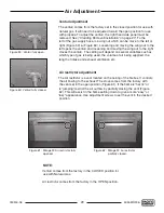
1. Position the glass retainer’s frame so
that the studs on unit align with holes
in frame. Secure using 12 3/8” nuts
(Figure 31).
CAUTION: Over tightening of nuts
could result in glass fracturing.
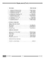
2. Insert and lower the outer door by
positioning the door’s pins into the
slits in the fi rebox frame (Figure 32).
Nuts
Slits
Fan Removal / Installation
Installation
1. Connect wiring to the fan and insert into the stove through the side of the unit.
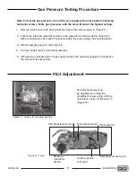
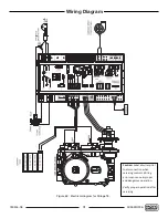
2. Insert both screws into the fan access panel to attach the fan to the unit (Figure 33).
3. Replace side cladding panel.
Removal
1. Start by turning off the main gas supply to stove and
disconnect the gas supply from the 1/2” fl are fi tting
(Figure 10). Also, disconnect the power cord from the
unit.
2. Remove 3 bolts (3/8” or Phillips) holding the side
cladding panel on your right hand side (Figure 53).
3. Remove the two (2) screws from the panel (Figure 33)
and pull the fan out of unit. You will have to disconnect
the wires from the fan before you can remove it
completely.
Figure 31: Glass retainer.
Figure 32: Outer door.
Figure 33: Fan install-removal.
Removal
1. Lift the outer door up and pull away
from unit.
2. Remove the 16 3/8” nuts
(Figure 31) Carefully remove the
glass retainer with the glass by tilting
the top towards you.
Summary of Contents for MIRAGE 30 SERIES A
Page 33: ...33 180516 36 5055 MR30 A ...
Page 34: ...34 5055 MR30 A 180516 36 ...
Page 35: ...35 180516 36 5055 MR30 A ...

