6
5055.MR30-A
180516-36
Minimum Clearance to
Combustible Materials
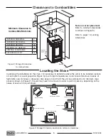
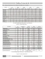
In planning the installation for the stove, it is necessary to determine where the unit is to be installed, location
of vent system or a wall projection (Figure 3). Due to high temperatures, do not locate this stove in areas of
high traffic, near furniture or draperies. Also keep in mind that if the unit is positioned to its’ minimum clear-
ances as shown in (Figure 2), the unit may need to be moved in order to perform service, depending on the
nature of service to be performed.
Locating the Stove
1”
4”
4”
4”
4”
4”
1”
1”
Vertical venting
Vertical venting
Vertical venting
Horizontal venting
Horizontal venting
4”
4”
4”
Vertical venting
36”
4”
36”
30”
front
4”
Note on corner placement
Refer to minimum clearances
as shown in (Figure 3).
Refer to page 7 for venting
allowances.
INTERIOR SIDE WALL
4”
INTERIOR BACK WALL
4”
INTERIOR CEILING
36”
IN FRONT OF HEATER
36”
VENTING CLEARANCE
1”
EXTERIOR SOFFIT
30”
Figure 2: Mirage 30 clearance
to combustibles.
Figure 3: Mirage 30 Common locations & minimum clearances.
Clearances to Combustibles
Summary of Contents for MIRAGE 30 SERIES A
Page 33: ...33 180516 36 5055 MR30 A ...
Page 34: ...34 5055 MR30 A 180516 36 ...
Page 35: ...35 180516 36 5055 MR30 A ...


