


6 SUPER-SD1
280514-24
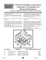
24”
610mm
24”
610mm
28”
711mm
28”
711mm
29 1/8”
740mm
29 1/8”
740mm
27 5/8”
702mm
23 5/8”
600mm
23 5/8”
600mm
23 5/8”
600mm
23 5/8”
600mm
10”
254mm
10”
254mm
10”
254mm
10”
254mm
23 7/8
606mm
23 7/8
606mm
28 3/8
721mm
27 1/2
699mm
27 1/2
699mm
29
737mm
29
737mm
27 1/2
699mm
28 1/4
718mm
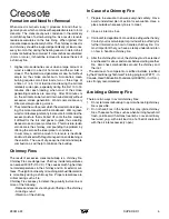
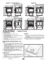
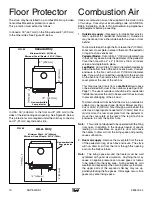
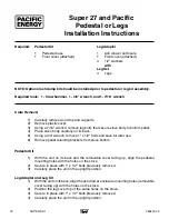
Super 27 - Pedestal Model
Spectrum
Super 27 - Leg Model
Spectrum Classic
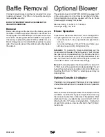
Leg Kit
1) With the unit on its back, align the ash drawer enclosure
mounting holes (removable cover facing up) with the holes
on the stove.
2) Position the legs over top of the same holes on the stove.
2) Secure in place with 1" x 1/2" bolts previously removed.
3) Carefully place the unit in the upright position.
- Super 27 only -
Assembly
Crate Removal
1) Carefully remove wood top and supports.
2) Remove plastic cover.
3) Using a 7/16" wrench, remove lag bolts that secure stove
body to bottom pallet.
4) Place stove body carefully on its back.
5) Using two 3/4" wrench, remove 1" x 1/2" bolts and save
for later use.
6) Remove pallet retaining brackets from stove bottom.
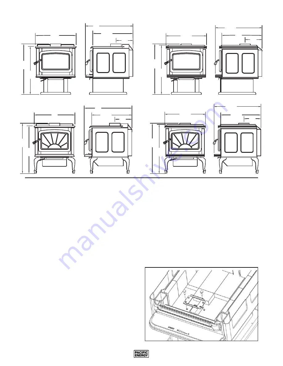
Optional Ash Cleanout System
-(Install
fi rst)
1) With stove body laying on its back, remove the ash system
hole cover and gasket located under the stove. Discard
cover plate and gasket.
2) Inside the stove, remove the two bolts for the ash dump
from the fi rebox bottom and insert into the brick retainer
with the fl anges on the the brick retainer pointed away
from the threads on the bolts.
3) Replace bolts with brick retainer in the fi rebox bottom.
4) Place new gasket provided over existing bolts.
5) Install ash dump system over gasket and secure with two
nuts previously removed.
Pedestal Kit
1) With the unit on its back and the removable cover facing
up, align the pedestal mounting holes with the holes on
the stove.\
2) Secure in place with 1" x 1/2" bolts previously removed.
3) Carefully place the unit in the upright position.
Summary of Contents for SPECTRUM
Page 20: ...20 SUPER SD1 280514 24...
Page 21: ...280514 24 SUPER SD1 21...
Page 22: ...22 SUPER SD1 280514 24...


