


280514-24
SUPER-SD1 9
Residential
Installation
Warning:
Under no circumstances is this heater to be installed
in a makeshift or "temporary" manner. It may be fi red only
after the following conditions have been met.
* DO NOT ATTEMPT TO CONNECT THIS HEATER TO
ANY AIR DISTRIBUTION DUCT.
* The services of competent installer are strongly recom-
mended.
* Outside combustion air or fresh air into the room may be
required in your area, consult local building codes (see
Combustion Air section).
- The services of a competent or certifi ed installer, (certifi ed
by the Wood Energy Technical Training program (WETT) - in
Canada, Hearth Education Foundation (HEARTH) - in U.S.A.,)
are strongly recommended.
BOTH CHIMNEY SYSTEM AND CONNECTOR MUST BE
LISTED TO: IN CANADA - ULC S-641 LISTED CONNEC-
IN CANADA - ULC S-641 LISTED CONNEC-
TOR AND ULC-S-629 LISTED CHIMNEY,
TOR AND ULC-S-629 LISTED CHIMNEY,
IN USA - UL-103
IN USA - UL-103
HT LISTED CONNECTOR AND CHIMNEY
HT LISTED CONNECTOR AND CHIMNEY
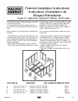
Clearances
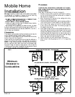
1. This heater may be installed using a single-wall connector
(smoke pipe) or listed double-wall connector (see Mobile
Home installation).
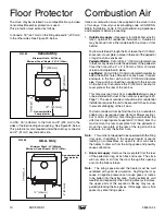
2. Clearances to combustible surfaces and materials using
single-wall connector are shown in Figure #1, page 6.
Clearances may be reduced with various heat insulating
materials. Consult local fi re codes and authorities for ap-
proval.
3. Alternately, for close clearances, use a listed double-wall
connector. See Diagram #1, page 6.
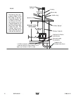
Chimney and Connector
Connect to a listed chimney or a chimney suitable for use
with solid fuel that is lined and in good condition and meets
local building codes. The chimney fl ue size should be the
same as the stove outlet for optimal performance. Reduc-
ing or increasing the fl ue size may adversely affect stove
performance. Chimney fl ue exit is to be 3 feet (1 m.) above
roof and two feet (0.6 m.) above highest projection within 10
feet (3 m.). The installation must meet all local codes. Do not
connect this unit to a chimney fl ue serving another appliance.
Minimum system height is 15 feet (4.6 m.) (measured from
base of appliance).
Double-Wall Connector
-
Use a listed double-wall connector.
-
Install all components to the chimney connector manu-
facturer's installation requirements.
Single-Wall Connector
Smoke pipe must be:
* as short and straight as possible, use six inch diameter,
24 gauge black pipe that is clean and in new condition.
* secured at every joint and collar with 3 sheet metal screws.
* installed with the crimped or male ends pointing down.
This will carry any liquid creosote or condensation back
into the stove.
* The chimney connector shall not pass through an attic, roof
space, closet or similar concealed space, fl oor, or ceiling.
Where passage through a wall, or partition of combustible
material is desired, the installation shall conform to CAN/
CSA-B365, Installation Code for Solid-Fuel-Burning Ap-
pliances and Equipment.
Procedure
1. If a listed chimney and double-wall connector is to be
connected to the stove, install all components to the chim-
ney manufacturer's installation requirements. (Outside
combustion air may be required, consult local building
codes. See Combustion Air section.)
2. If it is desirable to use smoke pipe in conjunction with the
insulated chimney, see step 4.
3. If a roof or ceiling support is used in the installation, you
will fi nd the chimney manufacturer's complete instructions
packed with the roof support.
4. To start installing smoke pipe (chimney connector), slip
crimped edge of the pipe inside the stove collar. Use
holes provided in collar to secure pipe with two screws.
5. Install the remaining lengths of pipe one on top of the
other to the fi nished height of the chimney connector and
secure to each other.
Summary of Contents for SPECTRUM
Page 20: ...20 SUPER SD1 280514 24...
Page 21: ...280514 24 SUPER SD1 21...
Page 22: ...22 SUPER SD1 280514 24...


