background image

12 

STEP.D1    090709-16

Optional Blower

The optional blower kit (kit #WODC.BLOW) is equipped 
with a three prong power cord and may be installed at 
any time. Follow installation instructions supplied with the 
kit. Route power supply cord away from heater.

Electrical rating:  115 volts A.C.-1.02 amps.
Fan output rating:  125 CFM

Blower Installation

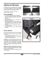
1.  Loosen the 2 screws at the center of the blower.
2.  Install  the  temperature  snap-switch  assembly  onto 

the blower by placing the bracket over the screws.
(Fig.#5)

3.  Tighten the screws.
4.  Ensure  that  the  two  wires  are  connected  to  the 

 temperature snap-switch.

5.  Slide the temperature snap-switch assembly up into 

the space between the rear shield and the firebox, 
ensuring that the temperature snap-switch contacts 
the firebox.

6.  Install the two screws through the flange of the blower 

into the rear shield.

7.  Plug  the  power  supply  cord  in  and  check  blower 

operation.

Blower Operation

Proper  blower  speed  matched  with  air  control  setting 
will ensure peak performance from your stove. Operate 
as follows:
 

- Air control set to low (right-most position), operate 
blower speed control on "Low".


- Air control set between low and high, operate blower 
speed control at desired setting.

Automatic:

  To operate the blower automatically, set the 

rocker switch on the side of the fan housing to "Auto" and 
set the speed control to desired setting. This will  allow 
the  fan  to  turn  on  as  the  stove  heats  up  to  operating 
temperature. It will also shut the blower off after the fire 
has gone out and the unit cooled to below a useful heat 
output range.

Manual:

  To manually operate the blower, set the rocker 

switch  to  "Man"  and  set  the  speed  control  to  desired 
 setting. This will bypass the temperature snap switch and 
allow full control of the blower.
Switching from "Auto" to "Man" or selecting speed may 
be done anytime.

Power Cord

Temperature

Switch

FIG. #5

FIG. #6

Summary of Contents for STEP D1

Page 1: ...tions Contact local building or fire officials about restrictions and installation inspection requirements in you area 090709 16 STEP D1 5055 2012 TESTED and LISTED to CAN ULC S627 AND UL 1482 Meets t...

Page 2: ...to follow instructions may result in property damage bodily injury or even death Contents Safety and Maintenance 3 Creosote 4 Formation and Need for Removal 4 Chimney Fires 4 In Case of a Chimney Fire...

Page 3: ...aintained in good condition Periodically inspect seals and replace if necessary Follow instructions included in the DR31 WDGKIT kit obtainable from your nearest Pacific Energy dealer 5 DOORGLASS Donot...

Page 4: ...solution The use of dry seasoned wood and ample combustion air will help to minimize the buildup Chimney Fires The result of excessive creosote buildup is a chimney fire Chimney fires are dangerous Ch...

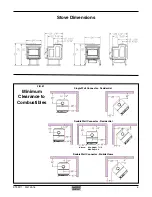
Page 5: ...090709 16 5 Stove Dimensions Double Wall Connector Mobile Home Alcove Min Height 7 1 2 Max Depth 4 Double Wall Connector Residential Single Wall Connector Residential Minimum Clearance to Combustible...

Page 6: ...t be installed with listed double wall con nector and compatible chimney system listed on page 7 Clearances to combustible surfaces and materials are shown in Figure 1 page 5 and Figure 2 page 7 Clear...

Page 7: ...tra Black 4 Selkirk Metalbestos Model DS 8 Simpson Dura Vent Model DVL B As well as one of the following compatible chimney systems All parts 6 CANADA ONLY Security Pro Jet ICC Selkirk Energy Vent S21...

Page 8: ...let for optimal performance Reducing or increasing the flue size may adversely affect stove performance Chimney flue exit is to be 3 feet 1 m above roof and two feet 0 6 m above highest projection wit...

Page 9: ...dislodging of the air duct Outside air may also be ducted from outside throughthe4 diameterholeintherearofthepedestal enclosure Note This unit is not designed to be operated with the firing door open...

Page 10: ...tove must be baked on with small fires When burning your stove for the first 2 3 times it is very important that the room be well ventilated Open all windows and doors Smoke and fumes caused by the cu...

Page 11: ...side pieces of insulation must be tight against the siderails WARNING Do not use grates or andirons to elevate the fuel Burn directly on the fire bricks Replace broken or missing bricks Failure to do...

Page 12: ...ear shield 7 Plug the power supply cord in and check blower operation Blower Operation Proper blower speed matched with air control setting will ensure peak performance from your stove Operate as foll...

Page 13: ...cessive Creosote Buildup See 1 2 3 above Low Heat Output 1 Wood is wet Use dry wood 2 Fire too small Build a larger fire 3 Draft too low Chimney plugged or restricted inspect and clean Won t Burn Over...

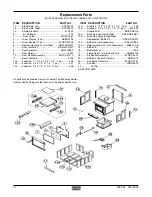
Page 14: ...brick 3 x 4 1 2 x 1 1 4 1 pc 247 12c Firebrick 4 x 4 1 2 x 1 1 4 1 pc 246 All parts may be ordered from your nearest Pacific Energy dealer Contact Pacific Energy for the location of the dealer nearest...

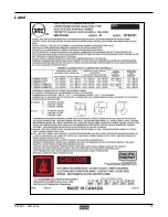
Page 15: ...STEP D1 090709 16 15 Label...

Page 16: ...PACIFIC ENERGY FIREPLACE PRODUCTS LTD 2975 Allenby Rd Duncan BC V9L 6V8 Phone 250 748 1184 Web site http www pacificenergy net...

Reviews: