background image

10                                                                                                                                                                       

SINC  250314-24

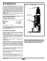
Surround Assembly and Installation

1)  Lay part A, B and C face down on a fl at,  non-marring 

surface.  Fasten together with 1/4" x 1/2" bolts and nuts 
provided through holes at points “D” (Fig. #8).

2)  Lift the surround assembly to the upright position and 

make sure the front face is fl at and even at the joints.

3)  Remove the two front panels as described on page 11 

and then remove the decorative top by loosening the two 
wing bolts underneath and sliding it out of the brackets.

 (Fig. 

#9).

4)  Slide the assembled surround from the top down and 

engage in slots on surround brackets. (Fig. #10 & 11).

5)  Push the entire appliance back until the surround assembly 

is in contact with the fi replace structure.

6)  Replace the decorative top and front panels.

7)  Position the decorative bay top onto the fi rebox top.  Align 

and refasten the wing screws.


Part B

 WING BOLTS

Part C

Part A

D

D

Fig. # 8

Fig. # 9

Fig. # 11

Fig. # 10

SURROUND SLOTS

SURROUND ENGAGED

IN  SLOTS

Summary of Contents for SUMMIT INSERT

Page 1: ...icials about restrictionsandinstallationinspectionrequirements in your area IMPORTANT THESE INSTRUCTIONS ARE TO REMAIN WITH THE HOMEOWNER SAVE THESE INSTRUCTIONS TESTED and LISTED to ULC S628 UL 1482...

Page 2: ...ney Fire 15 Avoiding a Chimney Fire 15 Maintenance 16 Baffle Removal 16 Appendix A 17 Understanding Operating Your Pacific Energy Stove 17 Troubleshooting 18 Firebrick Installation 19 Replacement Part...

Page 3: ...ly installed a house fire may result For your safety follow the instal lation directions Consult local building or fire officials about restrictions and installation inspection require ments in your a...

Page 4: ...et Baffle Top heat shield and mounting bolt Baffle Gasket Brick Rails Manifold Some warping of the baffle is normal up to 1 4 or 65cm Replace if the baffle has permanent warping greater than this or h...

Page 5: ...nt combustible floor Ember protection Combustible floor in front of the fireplace insert must be protected from hot embers by non combustible material extend ing 16 USA and 18 CANADA to the firing sid...

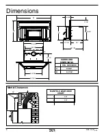
Page 6: ...14 24 Dimensions 40 7 8 23 5 16 25 3 8 27 9 16 B A 28 7 8 18 10 7 8 21 6 5 8 12 1 4 22 15 16 9 1 8 Mantel Clearances A 15 B 15 MANTEL CLEARANCE CHART A B 12 4 REG SURROUND A 48 3 4 B 32 1 16 SURROUND...

Page 7: ...urning use Check for creosote build up or other obstructions especially if it has not been in use for some time Have chimney swept Theexistingfireplacedamperistobelockedopenorremoved completely WARNIN...

Page 8: ...ove cement and insert into collar Screw in fasteners to secure 8 Attach a rain cap to the end of the liner A storm collar may be used if desired 9 Reattach casing top with screws previously removed Co...

Page 9: ...ir inlet or outlet ports This includes the circulating air chambers in a steel fireplace or metal heat circulator 5 Alteration of the fireplace in any manner is not permitted with the following except...

Page 10: ...age 11 and then remove the decorative top by loosening the two wing bolts underneath and sliding it out of the brackets Fig 9 4 Slide the assembled surround from the top down and engage in slots on su...

Page 11: ...and thermal snap switch Take note of where the wires are routed and secured They must be positioned correctly to avoid damage 3 Loosen the two bolts that secure the ash lip to the firebox carefully li...

Page 12: ...mounting bracket and relocate to left hand fan mounting bracket Fig 20 21 8 Reconnect the wires to the fans Fig 22 and thermal snap switch Fig 23 refit ash lip sides and top Ensure that the power cab...

Page 13: ...have shut the control down too soon or you are using too low a setting As every home s heating needs vary i e insula tion windows climate etc the proper setting can only be found by trial and error an...

Page 14: ...or on the ground well away from all combustible materials pending final disposal If the ashes are disposed of by burial in soil or otherwise locally dispersed theyshouldberetainedintheclosedcontaineru...

Page 15: ...ccurred If creosote has accumulated it should be removed to reduce the risk of a chimney fire 1 Highest smoke densities occur when a large amount of wood is added to a bed of hot coals and the air inl...

Page 16: ...s or any other volatile liquid to start a fire Do not burn garbage or flam mable fluids such a gasoline naptha or engine oil We strongly recommend that smoke detectors be installed 2 Remove ashes freq...

Page 17: ...ation The high mass weight acts as a heat storage and the thermal insulation keeps the combustion zone hot Active flaming takes place during the first part of the burn During this stage heat is stored...

Page 18: ...1 2 3 above Low Heat Output 1 Wood is wet Use dry wood 2 Fire too small Build a larger fire 3 Draft too low Chimney plugged or restricted inspect and clean Won t Burn Overnight 1 Air control is set to...

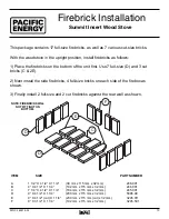
Page 19: ...mm x 32 mm 3245 501 Summit Insert Wood Stove This package contains 17 full size firebricks as well as 7 various cut size bricks With the woodstove in the upright position install firebricks as follow...

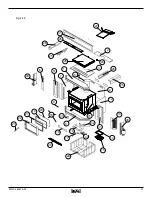
Page 20: ...ck CAST 46ST Door Casting Arched Gold CAST 46GDA Door Casting Arched Nickel CAST 46NI Door Casting Arched Brushed Nickel CAST 46BNA 23 Door Handle Assembly c w Wood Handle and Nut WODC 4147C 24 Baffle...

Page 21: ...SINC 250314 24 21 Fig 25...

Page 22: ...22 SINC 250314 24 NOTES...

Page 23: ...ICULATE EMISSION STANDARDS J LISTED SOLID WOOD FUEL FIREPLACE INSERT APPAREIL DU TYPE INSERTION DE COMBUSTIBLE SOLIDE DE CHEMIN E CERTIFIED FOR USE IN CANADA AND U S A CERTIFIE AU CANADA ET AUX ETATS...

Page 24: ...PACIFIC ENERGY FIREPLACE PRODUCTS LTD Phone 1 250 748 1184 www pacificenergy net 2975 Allenby Rd Duncan B C V9L 6V8 Printed in Canada...

Reviews: