


SUMMIT-B 091013-20
7
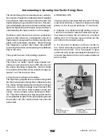
Procedure:
CAUTION: THE STRUCTURAL INTEGRITY OF THE MOBILE
HOME FLOOR, WALL AND CEILING/ROOF MUST
BE MAINTAINED.
THE SPACE HEATER IS TO BE CONNECTED TO A FACTORY-
BUILT CHIMNEY CONFORMING TO CAN/ULC-S629 STANDARD
FOR 650C FACTORY-BUILT CHIMNEYS.
Note: See "Combustion Air" section on page 9.
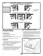
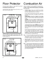
1. Position stove and fl oor protection with hole for combustion air
in accordance with the clearances as stated on the label and
in Figure #1.
2. Mark the position for the hole in the ceiling and roof by using a
string and plumb-bob.
3. Check that the intended location will not interfere with fl oor joists,
ceiling joists or rafters before proceeding further.
4. Cut a hole in the ceiling and roof to suit the chimney system
and frame in the sides. The chimney support is mounted to the
framing.
5. Assemble chimney sections so the fi nished length is resting on
the support and protruding through the roof. Avoid having joints
between ceiling and roof. Install radiation shield. Assemble
fl ashing and storm collar and be sure to maintain the vapour
barrier at this point. (Seal securely.) Attach rain cap and check
fl ashing for leaks.
6. Install connector as per manufacturer's instructions.
7. Attach stove to fl ooring using two 1/4" x 2" or longer lag
screws.
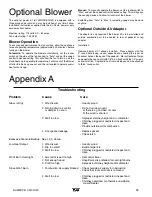
Mobile Home
Installation
Warning:
Under no circumstances is this heater to be installed in
a makeshift or "temporary" manner. It may be fi red only after the
following conditions have been met.
-
DO NOT CONNECT THIS UNIT TO A CHIMNEY FLUE SERVING
ANOTHER APPLIANCE.
-
DO NOT INSTALL IN A SLEEPING ROOM.
- Outside air supply must be used for Mobile Home installations
see Figure #3, Page 7.
- The services of a competent or certifi ed installer, (certifi ed by the
Wood Energy Technical Training program (WETT) - in Canada,
Hearth Education Foundation (HEARTH) - in U.S.A.,) are strongly
recommended.
Clearances
This heater must be installed with listed double-wall connector and
compatible chimney system listed on page 7.
Clearances to combustible surfaces and materials are shown in
Figure #1 and Figure #3, page 5 and 7.
Clearances may be reduced with various heat insulating materials.
Consult local, National fi re codes and authorities for approval.
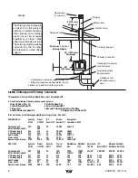
NOTE:
Longer chimney lengths and different pitch fl ashings
may be used. All other parts listed must be installed (see Figure
#3, Page 7). Install all components to the connector or chimney
manufacturer's installation requirements. Consult your chimney
supplier for installation advice.
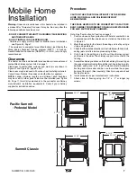
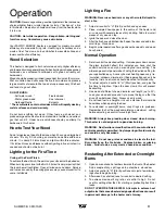
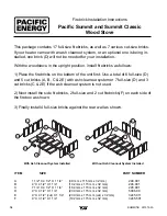
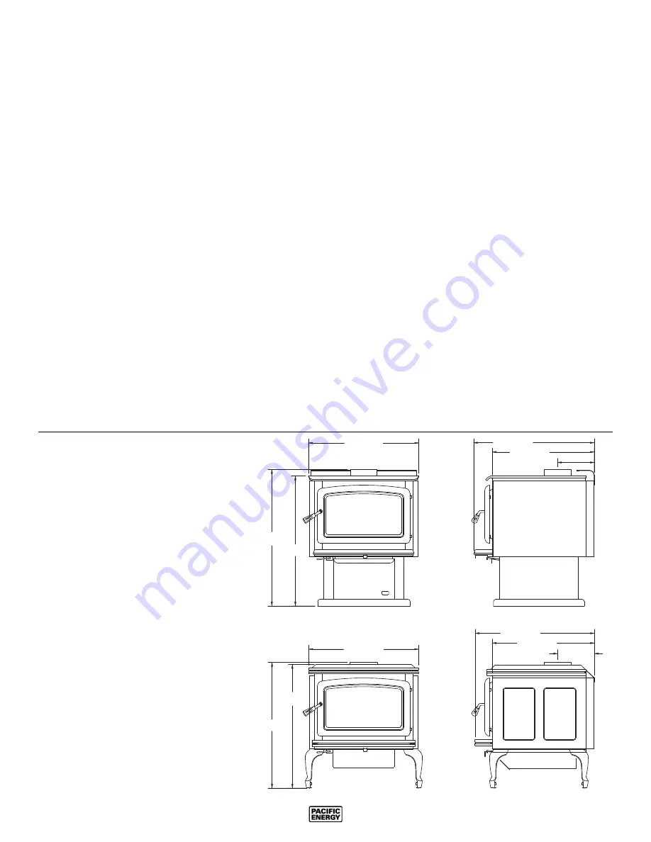
Pacifi c Summit
- Pedestal Model
31 1/2"
30"
25 1/2"
27 7/8"
23 1/2"
8 1/2"
29"
25 3/8"
8 1/2"
23 5/8"
28 1/2"
27 1/2"
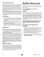
Summit Classic


