background image

SUMMIT-B   091013-20 

9

Residential 

Installation

Warning: 

Under no circumstances is this heater to be installed in 

a makeshift or "temporary" manner. It may be fi red only after the 
following conditions have been met.

*   

DO NOT ATTEMPT TO CONNECT THIS HEATER TO ANY AIR 
DISTRIBUTION DUCT.

*   

Outside combustion air or fresh air into the room may be required 
in your area, consult local building codes (see Combustion Air 
section).

- The services of a competent or certifi ed installer, (certifi ed by the 
Wood Energy Technical Training program (WETT) - in Canada, 
Hearth Education Foundation (HEARTH) - in U.S.A.,) are strongly 
recommended.

Clearances

1.  This heater may be installed using a single-wall connector 

(smoke pipe) or listed double-wall connector.

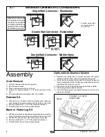
2.  Clearances to combustible surfaces and materials using single-

wall connector are shown in Figure #1, page 5.


Clearances may be reduced with various heat insulating materials. 
Consult local, National fi re codes and authorities for approval.

3.  Alternately, for close clearances, use a listed double-wall 

connector.  See Figure #1, page 5.

Chimney and Connector

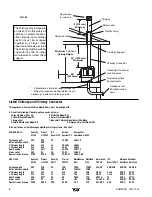
Connect to a listed chimney(in the U.S.A. a chimney complying with 
the requirements for Type HT chimneys in the standard for Chimneys, 
Factory-Built, Residential Type and Building Heating Appliance, UL 
103) and  a chimney suitable for use with solid  fuel that is lined and 
in good condition and meets local building codes. The chimney fl ue 
size should be the same as the stove outlet for optimal performance. 
Reducing or increasing the fl ue size may adversely affect stove 
performance. Chimney fl ue exit is to be 3 feet (1 m.) above roof and 
two feet (0.6 m.) above highest projection within 10 feet (3 m.). The 
installation must meet all local codes. Do not connect this unit to a 
chimney fl ue serving another appliance. Minimum system height is 
15 feet (4.6 m.) (measured from base of appliance).

Double-Wall Connector

Use a listed double-wall connector.

Install all components to the chimney connector manufacturer's 
installation requirements.

Single-Wall Connector

Smoke pipe must be:
*   as short and straight as possible, use six inch diameter, 24 

gauge black pipe that is clean and in new condition.

*   secured at every joint and collar with 3 sheet metal screws.
*   installed with the crimped or male ends pointing down. This will 

carry any liquid creosote or condensation back into the stove.

*   

The chimney connector shall not pass through an attic, roof space, 
closet or similar concealed space, fl oor, or ceiling. Where passage 
through a wall or partition of combustible material is desired, the 
installation shall conform to CAN/CSA-B365, Installation Code 
for Solid-Fuel-Burning Appliances and Equipment.

Procedure

1. 

If a listed chimney and double-wall connector is to be connected 
to the stove, install all components to the chimney manufacturer's 
installation requirements.  (Outside combustion air may  be 
required, consult local building codes.  See Combustion Air 
section.)

2.  If it is desirable to use smoke pipe in conjunction with the insulated 

chimney, see step 4.

3.  If a roof or ceiling support is used in the installation, you will 

fi nd the chimney manufacturer's complete instructions packed 
with the roof support.

4.  To start installing smoke pipe (chimney connector), slip crimped 

edge of the pipe inside the stove collar.  Use holes provided in 
collar to secure pipe with three screws.

5.  Install the remaining lengths of pipe one on top of the other to 

the fi nished height of the chimney connector and secure to each 
other with three screws per joint.

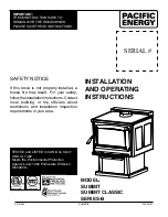
Summary of Contents for SUMMIT

Page 1: ...uctions Contact local building or fire officials about restrictions and installation inspection requirements in your area TESTED and LISTED to CAN ULC S627 AND UL 1482 Meets the Environmental Protecti...

Page 2: ...2 Baffle Removal 12 Removal 12 Secondary Air Box Removal and Cleaning 12 Optional Blower 13 Blower Operation 13 Optional Outside Air Adaptor 13 Appendix A 13 Troubleshooting 13 Understanding Operating...

Page 3: ...DR31 WDGKIT kit obtainable from your nearest Pacific Energy dealer 5 DOOR GLASS Do not slam loading door or otherwise impact glass When closing door make sure that no logs protrude to impact the glas...

Page 4: ...he Chimney System Top baffle board blanket Baffle Top heat shield and mounting bolt Baffle Gasket Brick Rails Manifold Blower The blower should be cleaned out a minimum every six months by using a vac...

Page 5: ...lution The use of dry seasoned wood and ample combustion air will help to minimize the buildup Chimney Fires The result of excessive creosote buildup is a chimney fire Chimney fires are dangerous Chim...

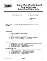
Page 6: ...sing a 3 4 wrench remove 1 x 1 2 bolts and save for later use 5 Remove pallet retaining brackets from stove bottom Pedestal Kit 1 With the unit on its back and the removable cover facing up align the...

Page 7: ...7 Attach stove to flooring using two 1 4 x 2 or longer lag screws Mobile Home Installation Warning Under no circumstances is this heater to be installed in a makeshift or temporary manner It may be f...

Page 8: ...mmander 5000 Ceiling support XSF FCS SF CF CSP CH6LCS Rafter radiation shield RRS 3 Chimney length XL3 SL3 L3 CF 36SL CH636 2 Chimney length XL2 SL2 L2 CF 24 CH624 Roof flashing XFA RF17 FA CF FRA CH6...

Page 9: ...tion within 10 feet 3 m The installation must meet all local codes Do not connect this unit to a chimney flue serving another appliance Minimum system height is 15 feet 4 6 m measured from base of app...

Page 10: ...be secured to the structure to prevent dislodging of the air duct To draw outside air from behind the stove an outside air adaptor may be required see Optional Blower section Cut or drill a 4 hole th...

Page 11: ...Place crumpled newspaper in the centre of the heater and criss cross with several pieces of dry kindling Add a few small pieces of dry wood on top 3 Ignite the paper and close the door 4 After the fir...

Page 12: ...ct air inlet setting is affected by variables such as type of wood outside temperature chimney size and weather conditions With practice you will become proficient in operating your heater and will ob...

Page 13: ...d with the kit Route power supply cord away from heater Electrical rating 115 volts A C 84 amps Fan output rating 125 CFM Blower Operation To ensure peak performance from your stove allow the applianc...

Page 14: ...this design Traditional wood stoves had a basic combustion system which allowed a considerable amount of heat energy to escape up the chimney as unburned gases and particulates smoke Pacific Energy ha...

Page 15: ...e Pin SSER 125001 14 Baffle Gasket SUMB 31396 15 Flame Shield c w Bolt and Nut SUMB 31155 16 Door Catch WODC 1461A 17 Secondary Air Box Gasket 5068 3237 18 Secondary Air Box c w Gasket SUMB 3140 19 Pe...

Page 16: ...001 15 Baffle Gasket SUMB 31396 16 Flame Shield c w Bolt and Nut SUMB 31155 17 Air Shutter Assembly SUMM 531 18 Ash Dump Assembly WODC 2261 19 Secondary Air Box Gasket 5068 3237 20 Secondary Air Box c...

Page 17: ...h remove 1 x 1 2 bolts and save for later use 6 Remove pallet retaining brackets from stove bottom Pedestal Kit 1 With the unit on its back and the removable cover facing up align the pedestal mountin...

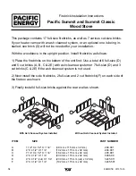
Page 18: ...ous cut size bricks If your heater came with an ash cleanout system or an optional one is being in stalled one brick D will not be needed for your installation With the woodstove in the upright positi...

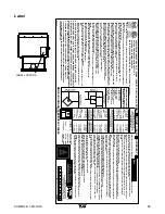
Page 19: ...127 MM I 0 INCHES 0 MM MOBILE HOME INSTALLATION USING DOUBLE WALL CONNECTOR INSTALLATION EN MAISON MOBILE UTILISANT UN RACCORD DE MUR DOUBLE WN 16391 ETL 4001507 INSTALLEZ ET UTILISEZ SELON LES INSTRU...

Page 20: ...PACIFIC ENERGY FIREPLACE PRODUCTS LTD 2975 Allenby Rd Duncan B C V9L 6V8 Phone 250 748 1184 Web site http www pacificenergy net Printed in Canada...

Reviews: