background image

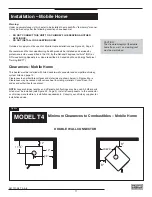
Installation Procedure – Mobile Home

CAUTION: THE STRUCTURAL INTEGRITY OF THE MOBILE HOME FLOOR, WALL 
AND CEILING/ROOF MUST BE MAINTAINED.

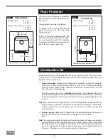
Note: See "Combustion Air" section on page 14

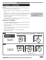
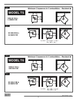
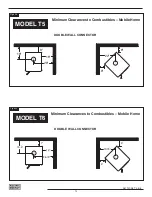
1.  Position stove and fl oor protection with hole for combustion air in accordance with the 

clearances as stated on the label and in Figures #4a–c.

2.  Mark the position for the hole in the ceiling and roof by using a string and plumb-bob.

3.  Check that the intended location will not interfere with fl oor joists, ceiling joists or rafters 

before proceeding further.

4.  Cut a hole in the ceiling and roof to suit the chimney system and frame in the sides. The 

chimney support is mounted to the framing.

5.  Assemble chimney sections so the fi nished length is resting on the support and pro-

truding through the roof. Avoid having joints between ceiling and roof. Install radiation 
shield. Assemble fl ashing and storm collar and be sure to maintain the vapour barrier 
at this point. (Seal securely.) Attach rain cap and check fl ashing for leaks.

5.  Install connector as per manufacturer's instructions.

6.  To attach stove to fl oor, fi rst remove the leveling bolts from the legs. Then attach stove 

to fl ooring using two 1/4" x  2" or longer lag screws through the leveling bolt holes.

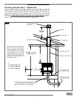
Listed Chimney and Chimney Connector for Mobile Home Installation

This appliance, when installed in a Mobile Home, must be installed with:

A. One of the following 6" double-wall connector systems:
  1. Security Model DL or DC   

5. Metal Fab Model DW

  2. Oliver MacLeod Model PV   

6. Ameri-Tec Model DBSP

  3. Energy Vent 


7. Industrial Chimney Model Excel Ultra-Black

  4. Selkirk Metalbestos Model DS 

8. Simpson Dura-Vent Model DVL

B. As well as one of the following compatible chimney systems - All parts 6":

CANADA ONLY: 

Security 

Pro-Jet 

ICC 

Selkirk 

Energy Vent


S2100 

H.T.3000 

Excel 2100  Sentinal CF  Commander 5000

Ceiling support 

XSF 

FCS 

SF 

CF-CSP 

CH6LCS

Rafter radiation shield 


RRS 

3' Chimney length 

XL3 

SL3 

L3 

CF-36SL 

CH636

2' Chimney length 

XL2 

SL2 

L2 

CF-24 

CH624

Roof fl ashing 

XFA 

RF17 

FA 

CF-FRA 

CH6TCF

Storm collar 

XSC 

SC 

SC 

CF-SC 

CH6SC

Spark arrestor rain cap  XCPE 

RCSA 

CPE 

CF-SA,CT 

CH6RC, SS

   
USA ONLY: 

Security 

Pro-Jet 

Security 

Pro-Jet 

Metalbestos  MetalFab 

Ameritech  ICC 

Simpson Dura-Vent


S2100 

H.T.3000 

ASHT 

HT3103 

SSII 

2100 

TEC HS 

Excel 103HT  Dura/Plus  Dura Tech

Ceiling support 

XSF 

FCS 

SF 

FCS 

T-SFA 

TGCSP 

6PL-CS 

RDS/SQS 

SDP-SB 

SDP-SB

Rafter radiation shield 


RRS 


RRS 

T-JSMH 

TGRS

3' Chimney length 

XL3 

SL3 

L3 

SL3 

T-36 

TG3 

HS 36 

CL48 

SDP-P 

SDT-P

2' Chimney length 

XL2 

SL2 

L2 

SL2 

T-24 

TG2 

HS 24 

CL24 

SDP-P 

SDT-P

Roof fl ashing 

XFA 

RF17 

FA 

RF 

T-SFA 

TGF 

8RFFU 

VF 

SDP-F 

SDT-F

Storm collar 

XSC 

SC 

SC 

SC 

T-SC 

TGSC 

PL-ASCG 

SC 

SDP-SC 

SDT-SC

Spark arrestor rain cap  XCPE 

RCSA 

CPE 

RCSA 

T-CT 

TGC 

6PL-MPC 

RCS 

SDP-C 

SDT-C

Follow chimney and chimney 
components manufacturer’s 
instruction for assembly and 
installtion.

13

261107-28 T4-5-6

Summary of Contents for T4

Page 1: ...UCTIONS INSTALLATION OPERATION GUIDE ALDERLEA CAST IRON WOOD STOVE MODELS T4 T5 T6 SAFETY NOTICE If this stove is not properly installed a house fire may result For your safety follow the installation...

Page 2: ...l of Ashes 18 Baffle Removal 18 Removal 18 Optional Blower 18 Blower Operation 18 APPENDIX A Troubleshooting 19 T4 Replacement Parts 20 T5 Replacement Parts 21 T6 Replacement Parts 22 Firebrick Instal...

Page 3: ...t must be replaced before using the stove Replacement glass can be obtained from your dealer Use ceramic glass only Do not substitute with any other type T4 16 250 x 10 5 x 5mm T5 17 25 x 11 395 x 5mm...

Page 4: ...over which the wood smoke is passing the more creosote will be condensed Wet or green wood contributes significantly to creosote formation as the excess moisture that is boiled off cools the fire maki...

Page 5: ...ere everyone is to meet If You Suspect a Chimney Fire Signs of a chimney fire may be one or more of the following 1 A roaring sound 2 Vibration of the chimney 3 Flames and sparks shooting out of the t...

Page 6: ...Fig 1 Appliance Dimensions MODEL T4 MODEL T5 MODEL T6 26 20 75 5 75 28 25 28 5 10 125 29 11 16 29 25 28 75 8 5 29 13 16 6 261107 28 T4 5 6...

Page 7: ...be reduced with various heat insulating materials Consult local fire codes and authorities for approval 3 Alternately for close clearances use a listed double wall connector See Figures 2a 2c 2e Insta...

Page 8: ...e Minimum Clearances to Combustibles Residential 22 12 18 30 25 11 11 20 16 26 14 15 5 10 16 18 28 4 4 Fig b SINGLE WALL CONNECTOR DOUBLE WALL CONNECTOR ALCOVE Min Height 7 1 2 feet Max Depth 4 feet F...

Page 9: ...eight is 15 feet 4 6 m measured from base of appliance CHIMNEY ROOF FLASHING STORM COLLAR 4 diameter air inlet with rodent screen If the crawl space is well ventilated it is not necessary to extend ai...

Page 10: ...form to CAN CSA B365 Installation Code for Solid Fuel Burning Appliances and Equipment Installation Procedure Residential 1 If a listed chimney and double wall connector is to be connected to the stov...

Page 11: ...by professionals who are certified in the U S by the National Fireplace Institute NFI as NFI woodburning Specialists or who are certified in Canada by Wood Energy Technical Training WETT Clearances Mo...

Page 12: ...Fig 4c DOUBLE WALL CONNECTOR Minimum Clearances to Combustibles Mobile Home 7 19 75 14 15 5 26 75 5 5 MODEL T6 8 28 18 16 8 22 8 Fig 4b DOUBLE WALL CONNECTOR Minimum Clearances to Combustibles Mobile...

Page 13: ...n installed in a Mobile Home must be installed with A One of the following 6 double wall connector systems 1 Security Model DL or DC 5 Metal Fab Model DW 2 Oliver MacLeod Model PV 6 Ameri Tec Model DB...

Page 14: ...diameter hole directly below the bottom knockout hole of the ash box enclosure Connect enclosure to the floor with a short 4 diameter pipe This hole must get its air from a ventilated crawl space or b...

Page 15: ...reshly cut hardwoods Wood should be properly air dried seasoned for six months or more Wet or undried wood will cause the fire to smoulder and produce large amounts of creosote Wet wood also produces...

Page 16: ...ol down too soon or you are using too low a setting As every home s heating needs vary based on insulation windows climate etc the proper setting can only be found by trial and error and should be not...

Page 17: ...Too much draft may cause excessive temperatures in the appliance An uncontrollable burn or a glowing red stove part or chimney indicates excessive draft 3 Inadequate draft may cause backpuffing into...

Page 18: ...ormance from your stove Operate as follows Air control set to low right position operate blower speed control on Low Air control set between low and high middle position operate blower speed control a...

Page 19: ...above Low Heat Output 1 Wood is wet Use dry wood 2 Fire too small Build a larger fire 3 Draft too low Chimney plugged or restricted inspect and clean Won t Burn Overnight 1 Air control is set too hig...

Page 20: ...R WASHER 12 DOOR CROWN 13 DOOR ADJUST PLATE 2 14 ASHLIP CASTING MBK 15 FIRE BOX 16 AIR SHUTTER ASSEMBLY 17 LEG ADAPTER 18 ASH PAN ASSEMBLY 19 OPTIONAL FAN 20 AIR DEFLECTOR 21 DOOR STOP 5 FIREBRICK SET...

Page 21: ...10 BOOST MANIFOLD 11 DOOR CATCH 12 DOOR WASHER 13 DOOR CROWN 14 DOOR ADJUST PLATE 2 15 ASHLIP CASTING MBK 16 FIRE BOX 17 AIR SHUTTER ASSEMBLY 18 LEG ADAPTER 19 ASH PAN ASSEMBLY 20 OPTIONAL BLOWER 21 A...

Page 22: ...16 1 BAFFLE KIT 1a BAFFLE 1b SIDE INSULATION 1c BAFFLE PIN 1d BAFFLE GASKET 2 BRICK RAILS 3 FLAME SHIELD 4 DOOR ASSEMBLY 4a DOOR HANDLE 4b DOOR CASTING MBK 4c HINGE PIN BRASS BUSHING 4d DOOR GASKET 4e...

Page 23: ...em or an optional one is being installed discard one full size brick With the heater in the upright position install firebricks as follows 1 Install 4 full size firebricks against the rear wall 2 Inst...

Page 24: ...TECH USE COMPONENTS SPECIFIED IN PACIFIC ENERGY INSTALLATION INSTRUCTIONS APPLIANCE MUST BE INSTALLED WITH PEDESTAL OR LEG KIT ATTACHED OPTIONAL COMPONENTS FAN KIT FAN ELECTRICAL RATING 115V 60HZ 80WA...

Page 25: ...ND BACK AS INDICATED MINIMUM CLEARANCES TO COMBUSTIBLE MATERIALS COMPONENTS REQUIRED FOR MOBILE HOME AND ALCOVE INSTALLATION OUTSIDE AIR KIT AND ONE OF THE FOLLOWING LISTED CONNECTORS SECURITY MODELS...

Page 26: ...ALLATION OUTSIDE AIR KIT AND ONE OF THE FOLLOWING LISTED CONNECTORS SECURITY MODELS DP OR DC OLIVER MACLEOD MODEL PV ENERGY VENT MODEL E VENT SELKIRK METALBESTOS MODEL DS METAL FAB MODEL DW AMERI TEC...

Page 27: ...27 261107 28 T4 5 6 Notes...

Page 28: ...PACIFIC ENERGY FIREPLACE PRODUCTS LTD Phone 1 888 715 2398 Web site www pacificenergy net 2975 Allenby Rd Duncan BC V9L 6V8 PRINTED IN CANADA...

Reviews: