background image

- 6 -

RETURN TO 

TABLE OF 

CONTENTS

SERVICING LEAD ACID BATTERIES WITH HYDROLINK

® 

WATERING 

SYSTEM

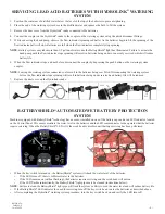
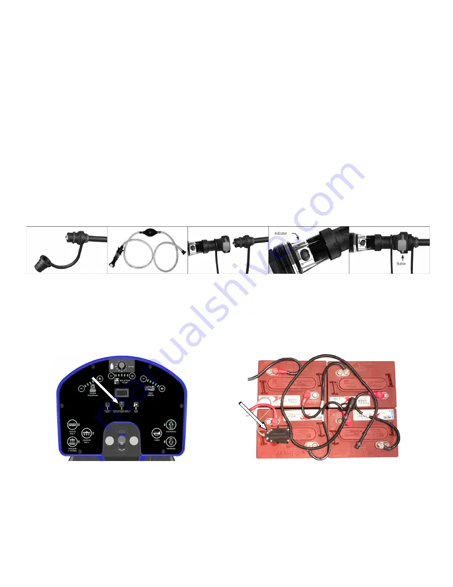
1.  Position the container of distilled water below the level of the top of the batteries to prevent siphoning.
2.  Place the end of the watering system hose in the distilled water and squeeze the bulb to fill the system.
3.  Remove the dust cover from the Hydrolink

®

 snake connected to the batteries.

4.  Connect the coupler on the Hydrolink

®

 snake to the coupler on the watering system using the quick disconnect fittings.

5.  While squeezing the hand pump, observe the flow indicator (spinning red balls). As the batteries begin to fill, the spinning of the 

flow indicator balls will slow. Batteries are full when the flow indicators completely stop spinning.

NOTE

: Battery systems may take more than 1/2 gallon of water once the BatteryShield

®

 light has illuminated. Failure to actuate the 

hand pump until the flow indicator stops spinning will result in batteries being under or unevenly serviced which will reduce 
battery life. 

6.  When the flow indicator stops, and not before, disconnect the coupler by depressing the push button on the watering system 

coupler. 

NOTE

: Leaving the watering system connected could result in the batteries being over filled. Disconnecting the watering system 

before the flow indicator stops spinning will result in batteries being under serviced and battery life will be reduced.

7.  Replace the dust cover on the Hydrolink

® 

snake.

BATTERYSHIELD

®

 AUTOMATED WET BATTERY PROTECTION 

SYSTEM

Machines equipped with BatteryShield

®

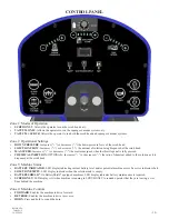
 technology have a sensor installed on one of the battery caps and a red LED indicator located 

on the Control Panel. This sensor monitors the water level in the batteries and the LED communicates to the operator that the batteries 

require servicing. When the BatteryShield

®

 LED is lit, the scrub head is disabled until battery servicing has been performed. 

• 

When the key switch is turned on, the BatteryShield

®

 system will check the water level of the batteries.

• 

If the LED turns off, there is sufficient water in the batteries.

• 

If the LED remains on (without flashing), the batteries require servicing and the scrub head will not run.

• 

If the LED flashes intermittently, the BatteryShield

®

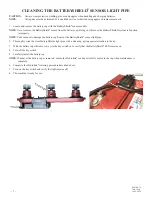
 light pipe must be cleaned (instructions below).

NOTE

:  Failure to clean the BatteryShield

® 

light pipe will limit the system’s ability to read the water level and will reduce battery life.

• 

If the BatteryShield

®

 LED indicates the need for servicing, turn off the key switch and service the batteries as described above.

• 

After completing the Hydrolink

®

 watering system procedure, turn the key switch back on and verify the LED turns off. 

Summary of Contents for RS28

Page 1: ...and keep it near the machine protected from liquids and other damaging substances Failure to follow the instructions may result in injury or damage to equipment and property The contents of this manua...

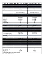
Page 2: ...n 71 1 cm 28 in 71 1 cm Pad Brush Size 2 14 in 35 6 cm Disk 14 in 35 6 cm x 28 in 71 1 cm Pad Pressure 90 lbs 40 8 kg 120 lbs 54 4 kg 150 lbs 68 kg 180 lbs 81 6 kg and 210 lbs 95 3 kg 90 lbs 40 8 kg 1...

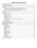
Page 3: ...ERVIEW 9 CONTROL PANEL 10 MACHINE ERROR CODES 11 DRIVE SYSTEM 12 SOLUTION DISTRIBUTION 12 SCRUB HEAD 14 ORBITAL SCRUB HEAD CHEMICAL FREE FINISH REMOVAL 14 DISK SCRUB HEAD 15 RECOVERY SYSTEM 16 RECOMME...

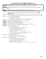
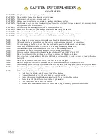
Page 4: ...ct battery cables before servicing WARNING Do not wear jewelry when working near moving or electrical components WARNING Do not use the machine as a means for transport WARNING Never allow children to...

Page 5: ...hine NOTE Use tie down straps to secure the machine to the truck or trailer during transport NOTE Discontinue use and report machine damage or faulty operation immediately NOTE Store the machine indoo...

Page 6: ...om the tie down straps located at each corner of the machine 5 Turn the machine on using the key switch and carefully drive down the ramp 6 Install the rear squeegee assembly refer to the RECOVERY SYS...

Page 7: ...vel surface and remove the key CAUTION Always wear protective clothing gloves and goggles when handling and charging batteries NOTE All repairs must be performed by a qualified service technician usin...

Page 8: ...ctrolyte sulfuric acid occurs flush with large amounts of water Use only distilled water tap water can contain contaminants that will damage the battery Remove the caps and place them upside down to c...

Page 9: ...eing over filled Disconnecting the watering system before the flow indicator stops spinning will result in batteries being under serviced and battery life will be reduced 7 Replace the dust cover on t...

Page 10: ...ion to the tip 3 With the battery cap still removed cycle the key switch on to verify that the BatteryShield LED remains on 4 Turn off the key switch 5 Carefully install the battery cap NOTE Whenever...

Page 11: ...plugged in can be viewed through the view window located on the vertical kick panel below the seat LED INDICATION MEANING GREEN flashing 2 seconds Charger is set for AGM batteries YELLOW flashing cont...

Page 12: ...ASSEMBLY L CUP HOLDER TOOL STORAGE M RECOVERY TANK N RECOVERY TANK LID O OPTIONAL LAMP P CHARGER STATUS VIEW WINDOW Q SEAT ADJUSTMENT R HOUR METER OPTIONAL LAMP SWITCH S SQUEEGEE HOSE T RECOVERY VACU...

Page 13: ...al is fully pressed CHEMICAL INJECTION OPTIONAL Increases or decreases the ratio of chemical added to the solution as it is dispensed at the scrub head Zone 3 Machine Status BATTERY INDICATOR LED disp...

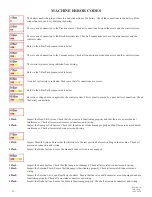
Page 14: ...E ERROR CODES 1 Flash Inspect the Head Lift System Check that the actuator is functioning properly and that there are no mechanical interferences Check all associated sensors connectors and wiring 2 F...

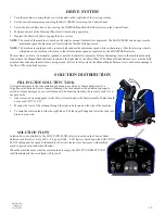
Page 15: ...ated on the right side of the Drive Wheel The Manual Brake Release lever must be fully actuated the entire time the machine is being moved Failure to fully actuate the Manual Brake Release lever could...

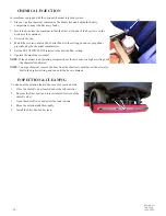
Page 16: ...l manufacturer 5 Set the SOLUTION FLOW selector to the desired flow setting 6 Operate the machine as normal NOTE If the chemical is not priming temporarily set the mix ratio to a higher setting until...

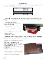
Page 17: ...UM SCRUB mode 4 Ensure the pad is properly aligned front to back and right to left Water should drip directly onto the top of the pad 5 Lower the Side Squeegees 6 The machine is ready for operation CH...

Page 18: ...head onto the pad driver assemblies by turning power onto the machine and selecting SCRUB ONLY or VACUUM SCRUB mode 4 Ensure the bayonet drivers are properly engaged with the pad driver assemblies 5...

Page 19: ...ponge to prevent mold and mildew 5 Inspect and clean the debris tray and the vacuum the mesh filter screen around the ball float system 6 Leave the lid open to dry The Tank Treatment System TTS uses B...

Page 20: ...will cause the squeegee assembly to lift and the vacuum motor to shut off after a 60 second delay This delay ensures all of the recovered water is pulled into the recovery tank SQUEEGEE ADJUSTMENT Imp...

Page 21: ...through the thickness of the blade Blades can be flipped and rotated to use all four edges 2 Thoroughly clean the blades frame and neck of any debris SQUEEGEE BLADE REPLACEMENT 1 Release the over cent...

Page 22: ...RINSE AIR DRY RECOVERY TANK X CLEAN INSPECT DEBRIS TRAY X VERIFY DRAIN HOSE CAP IS SEALED TIGHT WHEN INSTALLED X INSPECT LID SEAL X INSPECT REPLACE BROMINE PUCK X INSPECT HEPA FILTER X CLEAN SANITIZE...

Page 23: ...20 RETURN TO TABLE OF CONTENTS PAGE INTENTIONALLY LEFT BLANK...

Page 24: ...RIDER RECOVERY X X 894102 HOSE VACUUM RECOVERY RIDER RECOVERY X X X 555902 PAD 14 BLACK STRIP CASE 5 SCRUB HEAD X X 555909 PAD 14 X28 BLACK STRIP CASE 5 SCRUB HEAD X X 555929 PAD 14 X28 MAROON CFR CAS...

Page 25: ...URETHANE SQUEEGEE X X X X 890703 BLADE REAR 33 INCH LINATEX SQUEEGEE X X X 890704 BLADE FRONT 33 INCH LINARD SQUEEGEE X X X 898309 SPRING TORSION RH 40 IN LBS SQUEEGEE LIFT X X X 898310 SPRING TORSIO...

Page 26: ...S INSPECT AND REPLACE AS REQUIRED SQUEEGEE ASSEMBLY MAY BE OUT OF ADJUSTMENT ADJUST AS NECESSARY STUCK OR DAMAGED BALL FLOAT INSPECT AND REPAIR REPLACE RECOVERY TANK LID IS NOT SEALING PROPERLY INSPEC...

Page 27: ...ERENCE REPAIR SCRUB HEAD ACTUATOR POSITION SENSOR WIRING LOOSE OR DAMAGED INSPECT AND REPAIR CALIBRATION OF SENSOR IS REQUIRED MACHINE WILL NOT DRIVE MAIN FUSE MAY BE BLOWN INSPECT AND REPLACE IF PROB...

Page 28: ...4 WASHER SPLIT LOCK 31 SS 5 1 890802 BRACKET GUIDE HEAD 6 1 893202 FRAME WELDMENT RIDER 7 1 962296 SCREW BUTTON 31 18 X 3 50 SS 8 1 549701 WHEEL 5INCH 75 BEARING 9 1 898205 SPACER WHEEL BUMPER 10 1 89...

Page 29: ...24V 250MM 9 2 898202 SPACER PLATE HARNESS 10 1 890804 BRACKET MOUNTING CABLE 11 2 899003 TUBE HEAT SHRINK 3 1 ADHESIVE 05 X 2 5 12 1 890502 AXLE REAR RIDER SCRUBBER 13 1 920036 NUT NYLOCK 5 16 18 SS...

Page 30: ...820 BRACKET MOUNTING VALVE 8 4 980002 WASHER LOCK SPLIT 25 9 1 859402 VALVE SOLENOID 24V NONADJ 10 1 871501 CAP 38MM WITH HOLE 11 2 W189D SCREW HEX 1 4 20 X 75 SS PATCH 12 1 870811 BRACKET MTG HEAT SI...

Page 31: ...1 895114 LABEL GRIP FOOT 6 1 897004 PEDAL ASSY LOW PROFILE 7 1 896101 PLATE FOOT RIDER 8 1 894205 HOUSING DEBRIS PEDAL 9 1 893801 GROMMET PUSH IN FOR 1 5INCH 10 2 893302 FITTING ELBOW 5 NPT X 75 BARB...

Page 32: ...6 W243D WASHER FLAT 5 16 SS 13 1 891308 BLOCK BEARING STEERING 14 1 893201 FRAME COLUMN STEERING 15 1 S519PB SWITCH BLANKS BLACK TA 10 16 1 911661 METER HOUR DIGITAL 17 4 980094 WASHER SPLIT LOCK 31...

Page 33: ...YSHIELD 3 6 962263 SCREW BUTT SOCK 25 20X 62 SS BO 4 1 895101 LABEL CONTROL RIDER 5 1 897001 PANEL CONTROL OPERATOR 6 1 911621 METER BATTERY 7 2 920034 NUT NYLOCK 6 32 SS 8 6 878208 SPACER PLASTIC 10...

Page 34: ...CREW BUTT SOCK 25 20X 62 SS BO 12 1 894102 HOSE VACUUM RECOVERY 13 3 S611A CLAMP HOSE WORM 14 8 980002 WASHER LOCK SPLIT 25 15 8 W189D SCREW HEX 1 4 20 X 75 SS PATCH 16 2 920037 NUT THIN JAM 1 4 20 ZI...

Page 35: ...1 962269 SCREW HEX 31 18 X 75 SS 6 1 980094 WASHER SPLIT LOCK 31 SS 7 1 W243D WASHER FLAT 5 16 SS 8 1 892001 CLAMP LOOP RUBBER 1 75 INCH 9 4 W189D SCREW HEX 1 4 20 X 75 SS PATCH 10 4 980002 WASHER LOC...

Page 36: ...SHER NYL 50 X 1 25 X 062 7 4 980093 WASHER WAVE 50INCH 8 4 962465 SCREW SHOULDER 50 X 50 9 4 871101 BUSHING FLANGE 50IN 10 3 920035 NUT NYLOCK 38 16 SS 11 2 980094 WASHER SPLIT LOCK 31 SS 12 1 890811...

Page 37: ...RING COMPRESSION DIE 11 1 890201 ADAPTER ACTUATOR SHAFT 12 1 898307 SPRING COMPRESSION 62 D X 2 0 L 13 1 897301 RING RETAINING INTERNAL 62 DIA 14 1 896703 PIN DOWEL 50 DIA X 1 75 LONG 15 1 891501 CAP...

Page 38: ...0AH LA 3 0 NONE N A 4 1 878520 SENSOR ASSY BATTERYSHIELD FIELD REPLACE 5 1 857003 PUMP ASSY HND HYDROLINK 6 1 855605 MANIFOLD INDIV HYDROLINK BATT CAP 7 1 879002 COMPLETE SET MANIFOLD BATT CAP SERVICE...

Page 39: ...PORT CORD 2 1 893801 GROMMET PUSH IN FOR 1 5INCH 3 6 W401D WASHER FLAT 10 4 1 911645 HARNESS CHARGER POST 5 4 920666 NUT NYLOCK 10 32 SS 6 1 852407 CHARGER 24V ONBRD CULUS 7 1 920034 NUT NYLOCK 6 32 S...

Page 40: ...ER SEAT 12 1 962027 SCREW SHCS 31 24 X 625 ZINC 13 1 962279 SCREW SOCKET CAP 31X1 0 SS 14 1 980007 WASHER FLAT 31 ZINC 15 1 902050 BEARING ROD END 31 24 16 5 920036 NUT NYLOCK 5 16 18 SS 17 1 875103 L...

Page 41: ...R NYL 50 X 1 25 X 062 10 1 853802 GUIDE SPACER ROUND 11 1 898503 STAND COVER SEAT 12 1 962027 SCREW SHCS 31 24 X 625 ZINC 13 1 962279 SCREW SOCKET CAP 31X1 0 SS 14 1 980007 WASHER FLAT 31 ZINC 15 1 90...

Page 42: ...0OD 12THK SS 14 6 980094 WASHER SPLIT LOCK 31 SS 15 2 962466 SCREW HEX M8 1 25 X 25 SS PATCH 16 1 873802 GUIDE DRIVER RH 17 8 964448 SCREW HEX M6 X 16 SS PATCH 18 16 980002 WASHER LOCK SPLIT 25 19 8...

Page 43: ...RETURN TO TABLE OF CONTENTS 40 PAGE INTENTIONALLY LEFT BLANK...

Page 44: ...JAM SS 13 8 980094 WASHER SPLIT LOCK 31 SS 14 1 876609 PLATE MOUNTING MOTOR 15 8 851101 BUSHING RUBBER 16 8 980104 WASHER RUBBER 17 4 W117D SCREW HEX 25 20 X 2 0 SS 18 4 964009 SCREW SCK FLT M6 1 X 20...

Page 45: ...D 14 X28 WHITE POLISH CASE 5 AVAILABLE PADS ITEM QTY PART NUMBER DESCRIPTION 1 1 876607 PLATE ORBITAL 28 INCH 2 1 875903 PAD MIGHTYLOK ADH 14X28 3 12 962278 SCREW SOCKET FLT 31 18X 88 SS PATCH 4 4 980...

Page 46: ...ER 3 8 871101 BUSHING FLANGE 50IN 4 2 895105 LINK LIFT SQUEEGEE SIDE 5 2 891303 BLOCK MOUNTING SQUEEGEE SIDE 6 4 980093 WASHER WAVE 50INCH 7 2 895107 LINK SPRING SQUEEGEE SIDE RH 8 2 898308 SPRING EXT...

Page 47: ...71101 BUSHING FLANGE 50IN 4 2 895105 LINK LIFT SQUEEGEE SIDE 5 2 891306 BLOCK MOUNTING SQUEEGEE SIDE 6 4 980093 WASHER WAVE 50INCH 7 2 895106 LINK SPRING SQUEEGEE SIDE LH 8 2 898308 SPRING EXTENSION 5...

Page 48: ...CK 38 16 SS 14 2 871101 BUSHING FLANGE 50IN 15 2 962465 SCREW SHOULDER 50 X 50 16 1 962028 SCREW HX 38 24X 75 SS PTCH 17 1 890823 BRACKET SWING SQUEEGEE 18 5 898204 SPACER SQUEEGEE RIDER 19 5 980107 W...

Page 49: ...03 BLADE REAR 33 INCH LINATEX 2 1 890706 BLADE REAR 33 INCH URETHANE 3 1 897204 RETAINER SQUEEGEE REAR 33 INCH 4 1 890704 BLADE FRONT 33 INCH LINARD 4 1 890705 BLADE FRONT 33 INCH URETHANE 5 1 897205...

Page 50: ...R DESCRIPTION 1 1 892401 CONTROLLER DISK RIDER TRIO 1 1 892408 CONTROLLER ORBITAL RIDER TRIO 2 1 897003 PANEL ELECTRONICS RIDER 3 4 898201 SPACER PANEL ELECTRONICS 4 8 W104D WASHER FLAT 25 5 8 W189D S...

Page 51: ...CONTROLLER LEFT HAND BRUSH MOTOR 911749 HARNESS MOTOR SCRUB RH RIGHT HAND BRUSH MOTOR CABLE CONTROLLER RIGHT HAND BRUSH MOTOR 911752 HARNESS CONN BATTERY 4AWG BLACK BATTERY CONNECTION CABLE BATTERY BA...

Page 52: ...49 RETURN TO TABLE OF CONTENTS ELECTRICAL DIAGRAMS...

Page 53: ...RETURN TO TABLE OF CONTENTS 50 ELECTRICAL DIAGRAMS...

Page 54: ...RETURN TO TABLE OF CONTENTS 51 DATE MAINTENANCE LOG...

Page 55: ...52 RETURN TO TABLE OF CONTENTS DATE MAINTENANCE LOG...

Page 56: ...REVISION REVISION LOG 4 21 2021 UPDATED HARDWARE PG 34 ITEM 17 4 26 2021 UPDATED PART NUMBERS PG 45 ITEM 1 5 5 2021 UPDATED FOR CHANGES REFLECTED ON PG 36 AND 38 6 23 2021 ADDED NOTES ADDED BRAKE REP...

Page 57: ...54 RETURN TO TABLE OF CONTENTS PAGE INTENTIONALLY LEFT BLANK...

Page 58: ...www pacificfloorcare com...

Reviews: