background image

TABLE OF CONTENTS 


1.


SAFETY INFORMATION 


2.


UNPACKING THE MACHINE 


UNPACKING THE MACHINE 


3.


TRANSPORTING THE MACHINE 


TIE DOWN PROCEDURE 


4.


BATTERIES 


SELECTION AND INSTALLATION 


SERVICING LEAD ACID BATTERIES (NON-HYDROLINK® MODELS) 


SERVICING LEAD ACID BATTERIES WITH HYDROLINK™ WATERING SYSTEM 


BATTERYSHIELD® AUTOMATIC WET BATTERY PROTECTION SYSTEM 

10 


5.


CHARGING 

11 


ON-BOARD CHARGER 

11 


OFF-BOARD CHARGER 

12 


6.


PRE-USE SETUP 

13 


TURNING THE UNIT ON/OFF 

13 


BATTERY POWER LEVEL AND FAULT INDICATOR 
 

7.


DRIVE SYSTEM 

14 


DRIVING OPERATION 

14 


8.


SOLUTION DISTRIBUTION 

14 


FILLING THE SOLUTION TANK 

14 


SOLUTION FLOW: NON-CHEMICAL INJECTION MODELS 

15 


SOLUTION FLOW: OPTIONAL CHEMICAL INJECTION MODELS 

15 


FILTER INSPECTION AND CLEANING 

16 


9.


SCRUB DECK SETUP 

16 


HEAD LIFT 

16 


SELECTING DOWN PRESSURE 

16 


DISK MACHINE PAD DRIVERS AND BRUSHES 

17 


ORBITAL PADS 

18 


10.


RECOVERY SYSTEM 

19 


RECOVERY TANK 

19 


OPTIONAL TANK TREATMENT 

19 


SQUEEGEE BLADE INSPECTION AND SELECTION 

20 


SQUEEGEE ASSEMBLY SETUP 

21 


RECOMMENDED MAINTENANCE 

 22 

RECOMMENDED SERVICE PARTS 

23 

TROUBLESHOOTING GUIDE 

26 

PARTS DIAGRAMS 

28 

MAINTENANCE LOG 

58 

WARRANTY INFORMATION


59 


Summary of Contents for S-28

Page 1: ...ly and keep it near the machine protected from liquids and other damaging substances Failure to follow the instructions may result in injury or damage to equipment and property The contents of this ma...

Page 2: ...gal 95 l 3 gal 11 4 l demisting chamber 25 gal 95 l 3 gal 11 4 l demisting chamber 25 gal 95 l 3 gal 11 4 l demisting chamber 25 gal 95 l 3 gal 11 4 l demisting chamber Vacuum motor 7 hp 522 W 3 stage...

Page 3: ...TERY POWER LEVEL AND FAULT INDICATOR 7 DRIVE SYSTEM 14 DRIVING OPERATION 14 8 SOLUTION DISTRIBUTION 14 FILLING THE SOLUTION TANK 14 SOLUTION FLOW NON CHEMICAL INJECTION MODELS 15 SOLUTION FLOW OPTIONA...

Page 4: ...hen operating machine CAUTION Reduce speed when turning or operating on inclines and slippery surfaces CAUTION Use Bromine only in your tank treatment system Do not use chlorine Chlorine can interact...

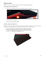
Page 5: ...n brackets holding the machine to the pallet 3 Raise the scrub head into the transport position 4 Use a suitable ramp or platform and carefully pull the machine backwards down from the pallet NOTE Use...

Page 6: ...S Series Scrubber was designed for easy transport on a route cleaning program 1 Raise the scrub deck 2 Raise and remove the squeegee assembly leave the recovery hose attached 3 Vertically position the...

Page 7: ...teries NOTE All repairs must be performed by a qualified service technician using approved replacement parts NOTE Batteries designed for automotive or marine and RV use are not suited for use in floor...

Page 8: ...nsulated tools and check connections for proper torque WATERING If contact with electrolyte sulfuric acid occurs flush with large amounts of water Use only distilled water tap water can contain contam...

Page 9: ...more than gallon of water after the BatteryShield LED has illuminated Failure to pump the HydroLink bulb until it will no longer compress may result in uneven battery servicing and premature battery f...

Page 10: ...ervicing and premature battery failure 3 After completing the HydroLink watering procedure cycle the key to verify the LED stays off CLEANING THE BATTERYSHIELD SENSOR LIGHT PIPE WARNING Do not wear je...

Page 11: ...is fully charged Solid YELLOW Phase 2 of charging is in progress Solid RED Charging cycle has begun NOTE Do not use an extension cord This will void the warranty on the charger SETTING THE CHARGER ON...

Page 12: ...the machine Up for Lead Acid batteries Down for sealed maintenance free AGM batteries 1 Connect the charger to the wall outlet 2 Connect the red plug pictured below to the battery harness below the c...

Page 13: ...wer level decreases the LEDs go out from right to left When the battery charge is depleted the last red LED will flash and the brush motor will turn off The vacuum and traction drive will continue to...

Page 14: ...uum motor In addition to properly mixed low foam detergent use a small amount of de foaming liquid in the recovery tank Never use pure acids NOTE The front fill port strainer blocks debris from fallin...

Page 15: ...p on 3 Match the mix ratio dial on the control panel to the setting in ounces per gallon prescribed on the chemical s container 4 Set the solution flow rate to low medium or high 5 A solid green LED i...

Page 16: ...ly eliminates overspray SELECTING DOWN PRESSURE 1 Standard For daily cleaning of normal soils 2 Medium For tough soils or chemical free finish removal 3 Heavy For toughest soils or chemical free finis...

Page 17: ...n tab side first Press the pad and release the wires so that they lock in place PAD AND BRUSH INSTALLATION 1 Turn the key switch on and rotate the speed control knob to the full slow position 2 Place...

Page 18: ...specialized surface preparation pad in addition to the traditional cleaning pad is required for chemical free finish removal The traditional pad acts as a backer pad and compensates for variances in...

Page 19: ...and clean the debris tray and the vacuum mesh filter screen and ball float system 6 Leave the lid open to dry OPTIONAL TANK TREATMENT The Tank Treatment System TTS utilizes Bromine tablets typically...

Page 20: ...SQUEEGEE USE 1 Lower Lift the squeegee lever shift it left and lower The vacuum motor will activate 2 Raise Lift the lever and shift it right The vacuum motor will run for 10 seconds to prevent recov...

Page 21: ...of the squeegee frame blades and neck REMOVE AND INSTALL THE SQUEEGEE BLADES 1 Release the latch and slide the retainer off the hook on the other side 2 Blades can be flipped length wise or top to bot...

Page 22: ...D SEAL RECOVERY SYSTEM X INSPECT REPLACE BROMINE PUCK IF EQUIPPED RECOVERY SYSTEM X INSPECT HEPA FILTER IF EQUIPPED RECOVERY SYSTEM X CLEAN SANITIZE RECOVERY TANK RECOVERY SYSTEM X INSPECT TERMINALS C...

Page 23: ...ADE REAR 35INCH URETHANE SQUEEGEE X X 870703 BLADE REAR 40INCH LINATEX SQUEEGEE X X X 870709 BLADE REAR 40INCH URETHANE SQUEEGEE X X X 870705 BLADE REAR 44 5INCH LINATEX SQUEEGEE X X X X X 870711 BLAD...

Page 24: ...BOWL FRAME ASSEMBLY X X X X X S764P2 FILTER STRAINER CHEMICAL INJECTION X X 223370 FLOAT SHUTOFF RECOVERY TANK X X X X 873314 GASKET FOAM VACUUM RECOVERY TANK X X X X 853803 GUIDE DRIVER SCRUB HEAD X...

Page 25: ...5921 PAD WHITE 14X28 10 CASE SCRUB HEAD X X 875903 PAD MIGHTYLOK ADH UNIVERSAL SCRUB HEAD X X 875906 PAD RETAINER 12X28 SCRUB HEAD X X 857003 PUMP ASSY HAND HYDROLINK NOT SHOWN OPTIONAL BATTERIES X X...

Page 26: ...ERY SYSTEM RECOVERY TANK LID IS NOT SEALING PROPERLY INSPECT RECOVERY LID GASKET REPAIR OR REPLACE IF NEEDED PARTS DIAGRAMS DRAIN HOSE CAP IS NOT INSTALLED PROPERLY INSTALL DRAIN HOSE SECURELY RECOVER...

Page 27: ...URE REDUCE DOWN PRESSURE SETTING PRE USE SETUP PAD IS TOO AGGRESSIVE FOR APPLICATION CONTACT YOUR LOCAL DISTRIBUTOR FOR RECOMMENDED APPLICATION PRE USE SETUP FAULTY OR SHORTED WIRE REPAIR WIRING DIAGR...

Page 28: ...BATTERY 6V 250AH MF NOT SHOWN OPTIONAL 3 1 858202 FOAM SPACER BATTERY 4 3 911640 HARNESS CONN BATTERY 5 1 911641 HARNESS CONN BATTERY 6 1 878509 SENSOR ASSY BATTERYSHIELD OPTIONAL 7 1 879002 TUBE PUM...

Page 29: ...PAN 10 32 X 1 0 SS 5 6 W401D WASHER FLAT 10 6 4 920666 NUT NYLOCK 10 32 SS 7 2 W104D WASHER FLAT 25 8 2 980002 WASHER LOCK SPLIT 25 9 1 920034 NUT NYLOCK 6 32 SS 10 2 962263 SCREW BUTT SOCK 25 20X 62...

Page 30: ...22 1 920012 NUT NYLOCK 5 16 18 ZINC 23 1 911653 SWITCH ROUND ON MOM 24 1 875124 LABEL CONTROL 22GAL DISK 25 1 911649 SWITCH ROCKER AUTO ON OFF 26 1 911661 METER HOUR DIGITAL 27 2 911664 POTENTIOMETER...

Page 31: ...NC 22 1 920012 NUT NYLOCK 5 16 18 ZINC 23 1 911653 SWITCH ROUND ON MOM 24 1 875124 LABEL CONTROL 22GAL DISK 25 1 911649 SWITCH ROCKER AUTO ON OFF 26 1 911661 METER HOUR DIGITAL 27 2 911664 POTENTIOMET...

Page 32: ...NYLOCK 4 40 ZINC 22 1 920012 NUT NYLOCK 5 16 18 ZINC 23 1 911653 SWITCH ROUND ON MOM 24 1 911661 METER HOUR DIGITAL 25 2 911664 POTENTIOMETER ASSY 5K 26 1 852401 CABLE LIFT CLEVIS 27 1 920038 NUT HEX...

Page 33: ...ONTROLLER DISPENSING 2 2 875001 KNOB 25 BORE SMALL 3 1 875104 LABEL CONTROL SOLUTION 4 1 875107 LED RED 24VDC 5 1 855115 LABEL BATTERYSHIELD WITH QR CODE 6 1 911684 HARNESS BATTERYSHIELD 7 1 911680 HA...

Page 34: ...912401 CONTACTOR 24V 100A 5 2 858501 STAND OFF INSULATED 25 20 6 6 W104D WASHER FLAT 25 7 6 980002 WASHER LOCK SPLIT 25 8 4 W169D SCREW HEX 25 20 X 50 9 2 W323D SCREW PAN 6 32 X 1 0 ZINC 10 2 980025 W...

Page 35: ...LOCK SPLIT 25 8 4 W169D SCREW HEX 25 20 X 50 9 2 W323D SCREW PAN 6 32 X 1 0 ZINC 10 2 980025 WASHER SPLIT LOCK 6 ZINC 11 4 W401D WASHER FLAT 10 12 6 962363 SCREW PAN 10 32 X 50 SS 13 6 980022 WASHER...

Page 36: ...LOCK SPLIT 25 8 4 W169D SCREW HEX 25 20 X 50 9 2 W323D SCREW PAN 6 32 X 1 0 ZINC 10 2 980025 WASHER SPLIT LOCK 6 ZINC 11 4 W401D WASHER FLAT 10 12 6 962363 SCREW PAN 10 32 X 50 SS 13 6 980022 WASHER...

Page 37: ...HIELD ELECTRONICS ITEM QTY PART NUMBER DESCRIPTION 1 2 980025 WASHER SPLIT LOCK 6 ZINC 2 1 911685 RELAY 24VDC BATTERYSHIELD 3 2 W315D SCREW PAN 6 32 X 50 BLK 4 2 980033 WASHER FLAT 6 SS 37 RETURN TO T...

Page 38: ...453P CLAMP HOSE WORM 14 1 224130 14 0 TUBING 1 2 15 1 843319 FILTER SCREEN BOWL 16 1 224130 5 12 TUBING 1 2 17 2 850807 BRACKET RETAINING TRANS 18 1 879203 TRANSAXLE 24VDC 19 1 870919 BRUSH KIT REPL F...

Page 39: ...ION 11 3 920035 NUT NYLOCK 38 16 SS 12 2 871101 BUSHING FLANGE 50IN 13 3 962465 SCREW SHOULDER 50 X 50 14 1 875002 KNOB PLASTIC LARGE 15 6 920012 NUT NYLOCK 5 16 18 ZINC 16 6 W243D WASHER FLAT 5 16 SS...

Page 40: ...WIRE TIE 9 1 S453P CLAMP HOSE WORM 10 4 962271 SCREW PAN 10 X 38L ZINC 11 1 875103 LABEL INSTRUCTION BATTERY 12 1 879401 VALVE SHUT OFF BALL 13 1 875011 KIT STRAINER PORT FILL 14 1 872304 COVER PORT...

Page 41: ...SCREW HEX 1 4 20 X 75 SS PATCH 11 2 962363 SCREW PAN 10 32 X 50 SS 12 2 980022 WASHER LOCK SPLIT 10 13 1 879003 42 0 TUBING 3 16 14 1 879003 10 0 TUBING 3 16 15 1 224130 1 62 TUBING 1 2 16 1 224130 3...

Page 42: ...REPL FOR 854101 18 1 854104 HOSE DRAIN CAPPED CHEM RESIST 19 1 872412 CABLE RETENTION MID LONG 20 4 W189D SCREW HEX 1 4 20 X 75 SS PATCH 21 8 964224 SCREW PAN 10 X 5 SELF TAPPING 22 1 853308 FITTING M...

Page 43: ...35INCH URETHANE 4 1 877203 RETAINER REAR 35 INCH 5 1 877204 RETAINER FRONT 35 INCH 6 2 859703 WHEEL GUIDE 7 3 962465 SCREW SHOULDER 50 X 50 8 4 920034 NUT NYLOCK 6 32 SS 9 3 920035 NUT NYLOCK 38 16 SS...

Page 44: ...AR 40INCH URETHANE 3 1 870704 BLADE FRONT 40INCH LINATEX 3 1 870710 BLADE FRONT 40INCH URETHANE 4 1 877201 RETAINER REAR 40 INCH 5 1 877202 RETAINER FRONT 40 INCH 6 2 859703 WHEEL GUIDE 7 3 962465 SCR...

Page 45: ...CH LINATEX 2 1 870711 BLADE REAR 45 INCH URETHANE 3 1 870706 BLADE FRONT 45 INCH LINARD 3 1 870712 BLADE FRONT 45 INCH URETHANE 4 1 877205 RETAINER REAR 45 INCH 5 1 877206 RETAINER FRONT 45 INCH 6 2 8...

Page 46: ...16 X 1 5 SS 9 1 962028 SCREW HX 38 24X 75 SS PTCH 10 1 870803 BRACKET SWING SQUEEGEE 11 1 877501 GUIDE ROLLER SQUEEGEE 12 2 962465 SCREW SHOULDER 50 X 50 13 2 871101 BUSHING FLANGE 50IN 14 1 962270 SC...

Page 47: ...876901 PULLEY IDLER 18 3 877302 RING RETAINING INT 1 12 DIA 19 6 878201 SPACER IDLER 20 3 878202 SPACER IDLER PLAIN 21 1 876902 PULLEY MOTOR DRIVE 22 1 980108 WASHER FLAT 31ID 1 25OD 12THK SS 23 1 915...

Page 48: ...1 4 20 SS 8 8 W104D WASHER FLAT 25 9 1 872305 SHROUD HEAD 24INCH 10 1 858503 SKIRT BRISTLE 11 13 962274 SCREW FLAT SOCK 25 20X 62 SS PATCH 12 2 873302 FITTING TEE PM02XBM04 13 2 875901 DRIVER PAD 12IN...

Page 49: ...012 NUT NYLOCK 5 16 18 ZINC 24 1 870804 BRACKET SUPPORT HEAD 25 4 871101 BUSHING FLANGE 50IN 26 4 962465 SCREW SHOULDER 50 X 50 27 2 873301 FITTING TEE 25INCH 28 2 876604 PLATE MOUNTING GIMBLE 29 2 98...

Page 50: ...HEAD 23 1 850906 BRUSH CARBON KIT 4 PC 855204 875201 24 4 871101 BUSHING FLANGE 50IN 25 4 962465 SCREW SHOULDER 50 X 50 26 2 873301 FITTING TEE 25INCH 27 2 876604 PLATE MOUNTING GIMBLE 28 2 980107 WAS...

Page 51: ...BER 13 2 857501 ROLLER PLASTIC 14 1 875205 MOTOR ORBITAL SERVICE 15 1 850906 BRUSH CARBON KIT 4 PC 855204 875201 16 4 W117D SCREW HEX 25 20 X 2 0 SS 17 2 962270 SCREW HEX 5 16 18X1 75 SS 18 1 915006 K...

Page 52: ...62 SS PATCH 6 1 964447 SCREW FLT M8 X 16 SS 7 12 962278 SCREW SOCKET FLT 31 18X 88 SS PATCH 8 1 876608 PLATE BALANCE 28 INCH 9 4 855604 MOUNT ISOLATOR 31THD 10 4 980108 WASHER FLAT 31ID 1 25OD 12THK...

Page 53: ...teryShield refer to the BatteryShield wiring diagram and instructions prior to proceeding If a yellow LED is flashing on the battery charger verify continuity between the charger and the battery pack...

Page 54: ...hield refer to the BatteryShield wiring diagram and instructions prior to proceeding If a yellow LED is flashing on the battery charger verify continuity between the charger and the battery pack A cir...

Page 55: ...Shield refer to the BatteryShield wiring diagram and instructions prior to proceeding If a yellow LED is flashing on the battery charger verify continuity between the charger and the battery pack A ci...

Page 56: ...BATTERYSHIELD OPTIONAL WIRING DIAGRAM 56 RETURN TO TABLE OF CONTENTS...

Page 57: ...CHEMICAL INJECTION OPTIONAL WIRING DIAGRAM 57 RETURN TO TABLE OF CONTENTS...

Page 58: ...58 MAINTENANCE LOG DATE MAINTENANCE PERFORMED RETURN TO TABLE OF CONTENTS...

Page 59: ...ormed regularly This warranty is in lieu of all other expressed or implied warranties and is extended to the original purchaser user only Orbital Scrub Head Isolators Isolator replacement parts on the...

Page 60: ...60 http www pacificfloorcare com RETURN TO TABLE OF CONTENTS...

Reviews: