background image

SKU 65322 or 65323  

For technical questions, please call 1-800-444-3353. 

Page 36

tenance  on  your  engine,  but  HFT  cannot  deny  warranty 

solely for the lack of receipts or for your failure to ensure the 

performance of all scheduled maintenance.
As the engine owner, you should, however, be aware that 

• 

HFT may deny you warranty coverage if your engine or a part 

has failed due to abuse, neglect, improper maintenance, or 

unapproved modifications.

You are responsible for shipping your engine to a HFT war-

• 

ranty station as soon as a problem exists.  Contact the HFT 

Customer Service department at the number below to make 

shipping  arrangements.   The  warranty  repairs  should  be 

completed in a reasonable amount of time, not to exceed 

30 days.
If  you  have  any  questions  regarding  your  warranty  rights 

and responsibilities, you should contact the Harbor Freight Tools 

Customer Service Department at 1-800-444-3353.

Harbor Freight tools emission control Defects 

Warranty Provisions

1.  Length of coverage

1. 

HFT warrants to a first retail purchaser and each subsequent 

purchaser that the engine is free from defects in materials 

and workmanship that cause the failure of warranted parts 

for a period of two (2) years after the date of delivery to the 

first retail purchaser.

2.  no charge repair or replacement

1. 

Repair or replacement of any warranted part will be performed 

at no charge to the owner if the work is performed through a 

warranty station authorized by HFT.  For emissions warranty 

service, contact the HFT Customer Service Department at 

1-800-444-3353.

3.  consequential Damages coverage

1. 

Coverage under this warranty shall also extend to the failure 

of any engine components caused by the failure of any war-

ranted part while it is still covered under this warranty.

4.  coverage exclusions

1. 

Warranty claims shall be filed in accordance with the provi

-

sions of the HFT warranty policy explained in the box at the 

top of the previous page.  HFT shall not be liable for any loss 

of use of the engine, for any alternative usage, for any damage 

to goods, loss of time, or inconvenience.  Warranty coverage 

shall also be excluded for any part which fails, malfunctions, 

or is damaged due to failure to follow the maintenance and 

operating instructions set forth in the Owner’s Manual includ-

ing, but not limited to:

Use of parts which are not authorized by HFT

a) 

Improper installation, adjustment or repair of the engine 

b) 

or of any warranted part unless performed by an autho-

rized warranty center
Failure to follow recommendations on fuel use contained 

c) 

in the Owner’s Manual
Improper or inadequate maintenance of any warranted 

d) 

parts
Repairs performed outside of the authorized warranty 

e) 

service dealers
Alterations by changing, adding to or removing parts 

f) 

from the engine.

5.  Service and maintenance

1. 

Component parts which are not scheduled for replacement 

as required maintenance or are scheduled only for regular 

inspection to the effect of “repair or replace as necessary” 

are warranted for the warranty period. Any warranted part 

which is scheduled for replacement as required maintenance 

is warranted for the period of time up to the first scheduled 

replacement point for that part.  Any replacement part, pro-

vided it is equivalent in durability and performance, may be 

used in performance of maintenance or repairs.  The owner 

is responsible for commissioning a qualified technician/me

-

chanic to perform all required maintenance, as outlined in 

the  Inspection,  Cleaning,  and  Maintenance  section  in  this 

manual.

6.  Warranted Parts

1. 

1)  Fuel metering System

Carburetor and its internal parts.

i) 

Fuel pump (if so equipped).

ii) 

Cold start enrichment system.

iii) 

2)  air induction System

Intake pipe/manifold.

i) 

Air cleaner.

ii) 

3)  ignition System

Spark plug.

i) 

Magneto ignition system.

ii) 

4)  catalyst System (if so equipped)

Exhaust pipe stud.

i) 

Muffler.

ii) 

Catalytic converter (if so equipped).

iii) 

5)  miscellaneous items used in above Systems

Vacuum,  temperature  and  time  sensitive  valves 

i) 

and switches.
Hoses, belts, connectors, and assemblies.

ii) 

record Product’s Serial number Here: 
note:

  If product has no serial number, record month and year of purchase instead.

note:

  Some parts are listed and shown for illustration purposes only, and are not avail-

able individually as replacement parts.

Summary of Contents for Pacific Hydrostar 2" or 3" Dirty Water Pump...

Page 1: ...tp www harborfreight com Read this material before using this product Failure to do so can result in serious injury Save this manual Copyright 2008 by Harbor Freight Tools All rights reserved No porti...

Page 2: ...e Schedule 16 Storage 17 18 Engine Troubleshooting 19 Pump Troubleshooting 19 Pump Parts List 20 Pump Assembly Diagram Page Contents 21 Crankcase Assembly Diagram and Parts List 22 Crankcase Cover Ass...

Page 3: ...which if not avoided could result in minor or moderate injury NOTICE is used to address practices not related to personal injury CAUTION without the safety alert symbol is used to address practices n...

Page 4: ...ose proximity to a heart pacemaker could cause pacemaker interference or pacemaker failure Caution is neces sary when near the engine s magneto or recoil starter Use only accessories that are recom 6...

Page 5: ...d feet away from 19 moving parts Do not reach over or across equipment while operating Before use check for misalignment 20 or binding of moving parts breakage of parts and any other condition that ma...

Page 6: ...ameter Model 65322 3 Model 65323 2 Maximum Flow in GPM Gallons per Minute Model 65322 345 Model 65323 235 Maximum Lift Suction Model 65322 26 Model 65323 23 Maximum Head Model 65322 85 Model 65323 82...

Page 7: ...or to use Additional inlet and outlet hoses and clamps not included will be needed depending on the specifics of use Remove the Pipe Clamps 13 from 2 both Inlet and Outlet Ports of the Pump Housing 10...

Page 8: ...tabilizer not included with 4 91 octane or better unleaded gaso line according to fuel stabilizer direc tions Fill the Fuel Tank to about 1 inch un 5 der the fill neck of the gasoline tank with the st...

Page 9: ...the Pump and or damaging the Pump Locate the pump as close to the wa 3 ter as possible The pump should be on a firm level surface Position the input and output hoses 4 as required Place the input hos...

Page 10: ...e Controls and Indicators Muffler Fuel Tank Cap Oil Dip Stick Oil Fill Port Oil Drain Plug Engine Switch Oil Dip Stick Note For clarity pump not shown Muffler Spark Plug Air Filter Oil Fill Plug Carbu...

Page 11: ...ean Insert the Dip Stick back into the hole without screwing it in Remove it again and check the oil level Full is indicated by oil on the Upper Level mark If adding oil use a siphon to avoid 3 spilli...

Page 12: ...s Valve to the 2 open right position Close the Choke by pulling 3 it to the left Note If the Engine is already hot it is 4 not necessary to close the Choke Push the 5 Throttle Lever to the slow right...

Page 13: ...00 RPM The emission control system for this engine is warranted for standards set by the U S Environmental Protec tion Agency For warranty information refer to the last pages of this manual Servicing...

Page 14: ...he filter If this does not get the filter reason ably clean replace it For foam filter elements b Wash the element in warm water and mild detergent several times Rinse Squeeze out excess water and all...

Page 15: ...valve before restarting the engine It may take a little longer than usual to start the engine be cause the fuel needs to refill the fuel line and new filter Cleaning Maintenance and Lubrication Sched...

Page 16: ...ll spark plug but leave spark d plug wire disconnected Pull recoil starter to distribute oil in e cylinder Stop after one or two revo lutions when you feel the piston start the compression stroke when...

Page 17: ...rk plug and set choke to start position Ignition spark Related Spark plug wire not connected 1 securely Spark plug electrode wet or dirty 2 Incorrect spark plug gap 3 Spark plug wire or spark plug 4 b...

Page 18: ...eaded gasoline Test replace fuel tank cap 3 Properly adjust idle speed 4 Have qualified technician diagnose 5 and service engine Engine knocks Old or low quality gasoline 1 Engine overloaded 2 Incorre...

Page 19: ...ut Gaskets 2 12 Input Output Pipes 2 Pump PARTS LIST Part Description Q ty 13 Pipe Clamp 2 14 Access Plug 2 15 Access Plug Gasket 2 16 O Ring 6 17 T Bolt 6 18 Basket Filter Connecting Pipe 1 19 Basket...

Page 20: ...SKU 65322 or 65323 For technical questions please call 1 800 444 3353 Page 20 Pump ASSEMBLY DIAGRAM...

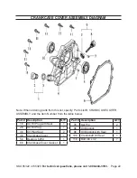
Page 21: ...Crankshaft Oil Seal 1 5a Crankcase 1 6a Regulator Sway Bar 1 7a Washer 2 8a Split Pin 1 9a Nut m10 1 10a Oil Sensor 1 Part Description Qty 11a Bolt m6 x 14 2 12a Regulating Shaft 1 13a Drive Gear Wash...

Page 22: ...1 2b Oil Fill Plug 1 3b Oil Plug Seal 2 4b Crankcase Cover 1 5b Bearing 6250 1 6b Crankcase Cover Gasket 1 Part Description QTY 7b Set Pin 2 8b Oil Dipstick 1 9b Oil Dipstick with Seal 1 10b Crankshaf...

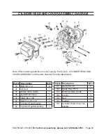
Page 23: ...ASSEMBLY and the Item Number from the table below Part Description QTY 1c Bolt m6 x 12 6 2c Air Duct 1 3c Intake Valve Guide 1 4c Lead Wind Cover 1 5c Stud m6 x 109 2 6c Set Pin m10 x 16 2 7c Cylinder...

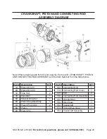
Page 24: ...1 6d Piston Ring Assembly 1 7d Piston Pin Circlip 2 8d Piston 1 9d Piston Pin 1 Part Description QTY 10d Connecting Rod 1 11d Connecting Rod Cover 1 12d Bolt 2 13d Connecting Rod Assembly 1 14d Woodru...

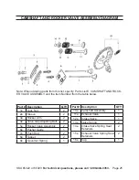
Page 25: ...d the Item Number from the table below Part Description QTY 1e Lock Nut 2 2e Sleeve 2 3e Rocker Arm 2 4e Valve Gap Adjusting Bolt 2 5e Rocker Valve Assembly 2 6e Pusher Guide 1 7e Push Rod 2 8e Tappet...

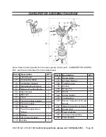
Page 26: ...nt Screw 1 5f Mixture Chamber Bode 1 6f Main Nozzle 1 7f Main Jet 1 8f Float 1 9f Float Chamber Gasket 1 10f Float Chamber 1 11f Washer 2 12f Float Chamber Drain Screw 1 13f Screw 1 14f Air Cleaner Ga...

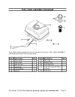
Page 27: ...FUEL TANK ASSEMBLY and the Item Number from the table below Fuel Tank Assembly Diagram Part Description QTY 7g Filter Cup 1 8g Packing Ring 1 9g Fuel Filler Cap 1 10g Fuel Filler Cap with Pack ing Ri...

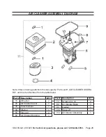
Page 28: ...AIR CLEANER ASSEM BLY and the Item Number from the table below Air Cleaner Assembly Diagram Part Description QTY 1h Wing Nut 2 2h Air Cleaner Cover 1 3h Filter Element 1 4h Washer 1 5h Sleeve A 2 6h...

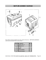
Page 29: ...e 29 Muffler Assembly Diagram Note When ordering parts from this list specify Parts List J MUFFLER ASSEMBLY and the Item Number from the table below Part Description QTY 1j J Screw m5 x 8 4 2j Muffler...

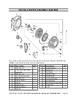
Page 30: ...Part Description QTY 1k Bolt m6 x 22 1 2k Crankcase Side Plate Assembly 1 3k Bolt m6 x 18 3 4k Fan Hood Assembly 1 5k Bolt m6 x 12 5 6k Engine Switch 1 7k Casing 1 8k Spiral Spring 1 9k Ratchet Spring...

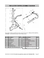
Page 31: ...SSEMBLY and the Item Number from the table below Part Description QTY 1l Nut m6 1 2l Setting Panel 1 3l Patch Spring 1 4l Hand Grip 1 5l Washer 1 6l Bolt m5 x 25 1 7l Regulating Spring 1 8l Support Pa...

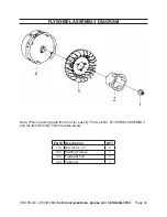
Page 32: ...00 444 3353 Page 32 Note When ordering parts from this list specify Parts List M FLYWHEEL ASSEMBLY and the Item Number from the table below Flywheel Assembly Diagram Part Description QTY 1m Nut m14 x...

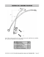
Page 33: ...When ordering parts from this list specify Parts List N IGNITION COIL ASSEM BLY and the Item Number from the table below Ignition Coil Assembly Diagram Part Description QTY 1n Screw m6 x 22 2 2n Engi...

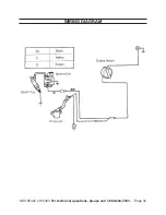
Page 34: ...SKU 65322 or 65323 For technical questions please call 1 800 444 3353 Page 34 Wiring Diagram...

Page 35: ...f we determine there is no defect or that the defect resulted from causes not within the scope of our warran ty then you must bear the cost of returning the product This warranty gives you specific le...

Page 36: ...ge to goods loss of time or inconvenience Warranty coverage shall also be excluded for any part which fails malfunctions or is damaged due to failure to follow the maintenance and operating instructio...

Reviews: