


5
Electrician Installation Manual
EM-E Ceiling Fan
1.
Do not
attempt to operate the fan (or optional light kit) with any wall control that is not
approved by Pacific International Fans for use with its fans. DO NOT use solid state
controllers. The use of unapproved controllers will void your warranty.
2.
Do not
mix blade sets from one fan to another as this may upset the balance of the fan. If
only one blade is damaged you are still required to replace with a new set.
Assembling the fan
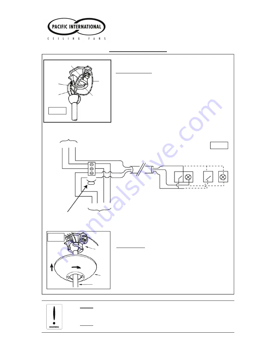
Fig. 4
Green
Earth Wires
STEP 4 (Fig 4 & 5)
a)
Connect wires from the fan to wires in the ceiling via the
terminal block on the hanger bracket (refer to figure 4 and 5).
b)
Make sure earth wires are also connected.
c)
Connect light wires (red/white) if a light fitting is going to be
used. (Cap seal light wires if a light fitting is not going to be
used).
Wiring Instructions (with and without accessory light)
Brown
Blue
Red/White
Earth
Wires
Supply
E N A
LA
LA
FA LA E N
Gree
n-
yellow
Black
Red
Red
Red
Bro
w
n
White or Red
Gree
n-
yellow
Blue
Fan Wiring
Combi
Control
Separate
Control
Separate terminal
For when 3 pole
Block is fitted.
Wiring for use with 3 pole block
- Colours representative only
- Separate extension terminal for active
for light when 3 pole block fitted.
Fig. 5
STEP 5 (Fig 6)
a)
Slide canopy cover up and over the hanger bracket.
b)
Twist the canopy to locate screws holes then loosen
canopy screws half way.
c)
Now twist the canopy cover in the
opposite direction and fully tighten screws until the can-
opy cover is stabilised.
Fig. 6
Hanger
Bracket
Canopy Cover
Down Rod


