®
I N C .
P A C I F I C
M I C R O S O N I C S
9
I
nstallation
Model Two HDCD
®
User’s Manual
Rev. C - January 2002
POWER
P A C I F I C
M I C R O S O N I C S
UP
DOWN
MENU
METER
RESET
1
6
7
8
9
10
11
12
2
3
4
5
SYSTEM
CLOCK
A/D
D/A
ENTER
Model Two Processor Description
The Processor is contained in a 3 R.U. (5.25”) high, 19” wide X 19.25” deep, rack mount
enclosure with adjustable rear rack ears. The Processor contains the following subsystems:
Analog to Digital Converter (ADC), Digital Signal Input/Output (DIO), Digital Signal Pro-
cessor (DSP), Digital to Analog Converter (DAC), and Front Panel Controller (FPC). The ADC
converts 2 channels of analog signals to digital at a sampling frequency of 192 kHz or
176.4 kHz. The DIO receives and transmits AES3 data, word clock, and RS-232 serial data.
The DSP performs all HDCD encoding, decoding, frequency and word length conversion,
digital signal gain changes, etc., employing eight Motorola 56009 Digital Signal Proces-
sors and one Pacific Microsonics PMD-100 HDCD Process Decoder ASIC. The DAC converts 2
channels of 24-bit to 16-bit digital data to analog signals. The FPC provides the interface
between the DSP and the front panel graphic display, signal level meters, and controls.
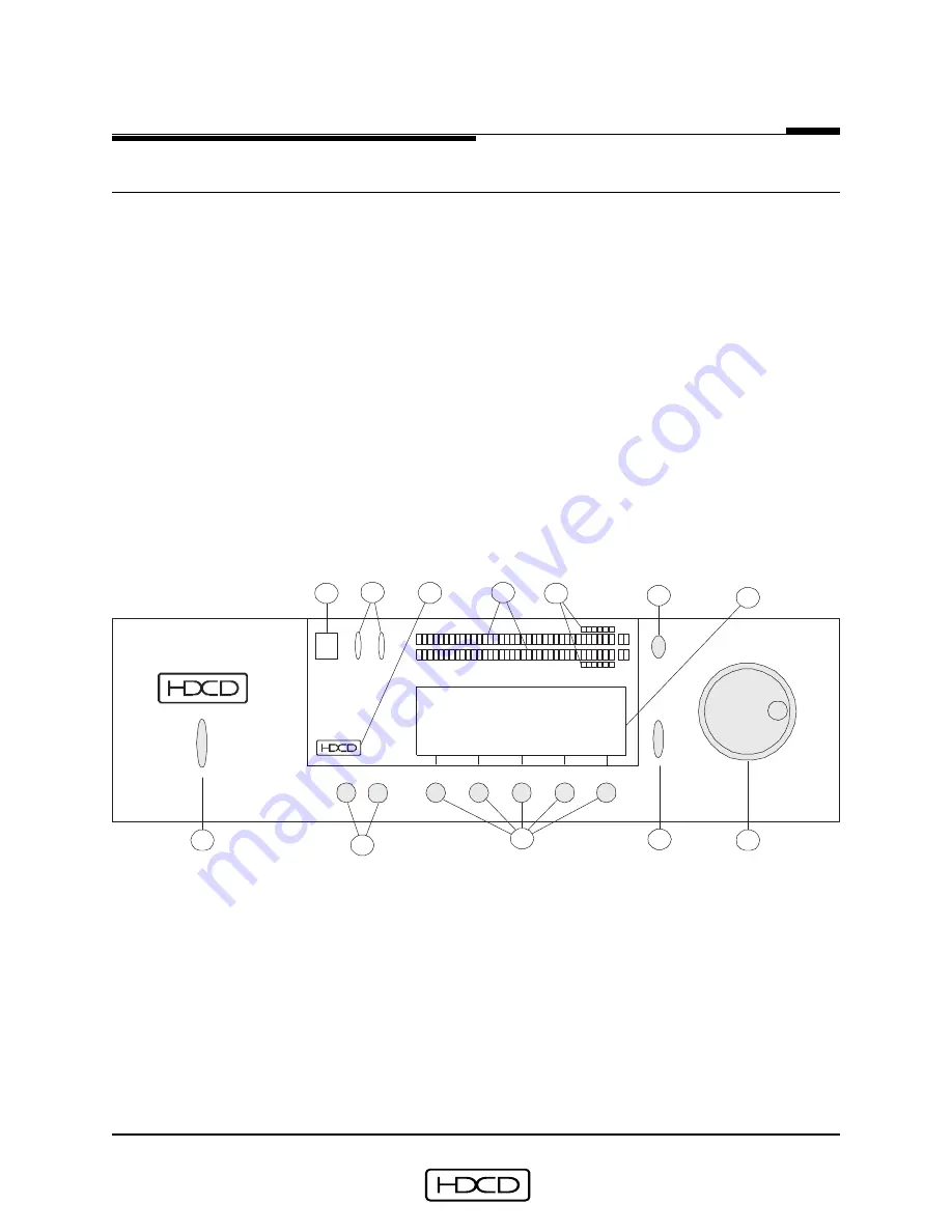
All Processor controls, except the Analog Input Attenuator, are located on the front panel
as shown below:
1
“POWER” Switch
7
“CLOCK” Indicators
2
“MENU” “UP” and “DOWN” Buttons
8
“HDCD”Indicator
3
Function Buttons 1-5 (left to right)
9
Signal Level Meters
4
“ENTER” Button
10
Peak Extension Meters
5
Rotary Control
11
“METER RESET” Button
6
“SYSTEM” Status Indicator
12
Graphic Display


