LMX SERIES™ OPERATION MANUAL
SECTION 7: Auxiliary I/O
Error! Reference source not found.
Entire Contents Copyright
2018 by Pacific Power Source, Inc. (PPS) • All Rights Reserved • No reproduction without written authorization from PPS.
LMX Series Power Source Operation Manual
Page 191 of 463
7.8.2
Programming Analog Inputs
The range of the analog inputs can be changed with two parameters for each input, gain and
offset. For example if an input is assigned to AC voltage programming the default gain is
300V and the offset is 0V. This means that 10V at the analog input port represents a
programmed voltage of 300Vrms and 0V represents 0Vrms.
Different gain and offset combinations can be used to customize the range of the analog
programming input, being the “gain” the programmed value that represents the maximum
input at the analog port, and “offset” the value at 0V. For example, a gain of 150V and offset
of 50V produce an output of 50V to 200V for analog programming signals of 0V to 10V.
Note:
Different LMX parameters have different units (Volts, Amperes, Watts, Hertz, etc.),
so when an analog input parameter is changed, the gain and offset are reset to
default values (zero for offset and max full-scale values for gain).
7.8.3
Analog Outputs
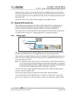
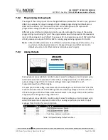
ANALOG
OUTPUTS
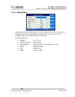
Analog outputs are available to monitor output values for voltage, current or power using
external measurement equipment. A total of four analog outputs are provided, with an
output voltage range of 0 to 5V. Output scaling is fully programmable for each
measurement with an offset and gain.
For example, for RMS voltage measurements the default gain is 300V and offset is 0V. This
means that measurements of 0 to 300V generate monitoring voltages of 0 to 5V. An offset
of 50V and a gain of 150V will mean that measurements in the range of 50 to 200V will be
mapped to the analog output range of 0 to 5V.
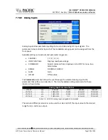
Analog outputs are available to monitor output values for voltage, current or power using
external measurement equipment. A total of four analog outputs are provided. Output
scaling is from 0 to 10V for zero to full scale.
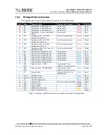
Pin #
Signal
Programs
22
AO1
Volt RMS Measurements Phase A
23
AO2
Volt RMS Measurements Phase B
24
AO3
Volt RMS Measurements Phase C
25
AO4
Total Power (all phases combined)
Table 7-3: Default Analog Output Functions

