LMX SERIES™ OPERATION MANUAL
SECTION 7: Auxiliary I/O
Error! Reference source not found.
Entire Contents Copyright
2018 by Pacific Power Source, Inc. (PPS) • All Rights Reserved • No reproduction without written authorization from PPS.
LMX Series Power Source Operation Manual
Page 199 of 463
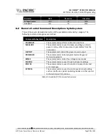
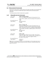
Events that can be assigned to digital outputs are listed in the table below and can be set
using the
Function
field.
Digital Output Assignable Events
EVENT
Description
Indication
FAULT
Output goes high on fault event
1 = Fault occurred, 0 = No Fault
FORM
Output FORM state
1 = SINGLE, 0 = SPLIT/THREE
HIGH
Fixed Output high
1 = ON
LOW
Fixed Output low
0 = OFF
OUTPUT STATE
Output Relay State
1 = ON (enabled), 0 = OFF (disabled)
PROGRAM
Output goes high when Program is selected
1 = Steady State Program, 0 = Manual mode
REMOTE
Output goes high when unit is in REMOTE state 1 = REMOTE state, -0 = LOCAL state
TRANSIENT
Output goes high when transient is running
1 = Running/Paused/Stepping, 0 = Stopped
XFMR_COUPLING
Indicates output coupling mode
1 = Transformer Coupled, 0 = Direct Coupled
Table 7-5: AUX I/O Digital Output assignable Events or Conditions
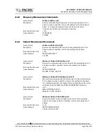
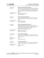
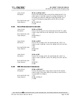
7.12.6
Polarity Selection for DO3 and DO4 vs DO1 and DO2
The two open drain outputs DO3 and DO4 have internal 1 kΩ pull
-up resistors to +5.5V.
These outputs can be used as regular digital outputs (open-drain type) if needed. However,
the logic will be inverted because a “direct” logic for the relay drive means an “inverted”
logic for the open drain output. The FET being on means the relay coil active, but with a pull-
up the output goes to low.
DO3 and DO4 use direct logic for the relay drive, which means that if the inverting logic is
not active and there is a “1” written to the digital output, an internal FET will be activated
causing a “low” in the open drain output.
Each digital output can be configured to have separate inverting logic, so the user can
configure these 2 to be inverting and have the normal direct logic when used as open-drain
outputs.

