LMX SERIES® OPERATION MANUAL
Entire Contents Copyright
2018 by Pacific Power Source, Inc. (PPS) • All Rights Reserved • No reproduction without written authorization from PPS.
LMX Series Power Source Operation Manual
Page 86 of 463
5.14.5
System Interface Bus Connectors
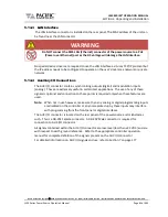
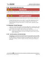
WARNING
SHOCK HAZARD: DO NOT remove safety covers from the two System Interface DVI Connectors.
AVERTISSEMENT
RISQUE DE CHOC: NE PAS retirer les capots de sécurité des deux connecteurs d´interface DVI
The system interface bus is not user-accessible. It consists of two Digital Visual Interface
(DVI-I dual link) connectors that are covered by a protective cover. There are no user
accessible signals on the system interface bus. It is used for system configuration cabinet
systems only.
5.15
Multi-Unit Parallel Operation
Two or more 140, 160, 345 or 360LMX units can be configured as a parallel system to create
a high power system. This requires at least one Master LMX unit and one or more Auxiliary
units or Master units that will be used as Auxiliaries to the first Master.
Note:
Auxiliary units or Master units used in an auxiliary position must be of the same
power output as the Master unit so each unit delivers the same amount of current
/power into the load.
5.15.1
Load Connections on Parallel Systems
Paralleling two or more units requires that their outputs are tied together using load cables
of
equal length
from each unit to the load. A common coupling terminal block may be used
to combine outputs in combination with larger size load wires to the load. Make sure the
appropriate size wiring is used for the higher current levels obtained by paralleling two or
more units.

