ADF SERIES® OPERATION MANUAL
SECTION 5: UNPACKING AND INSTALLATION
Entire Contents Copyright
2018 by Pacific Power Source, Inc. (PPS) • All Rights Reserved • No reproduction without written authorization from PPS.
ADF Series Power Source Operation Manual
Page 73 of 349
5.17
Cabinet System Options
The following cabinet option is available. If your cabinet was not furnished with this option,
you can skip to Section 5.18, “Interface Options”.
5.17.1
-OCS: Output Control Switch Option
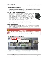
The output control switch option adds an output control selector switch
on a 1U filler panel located directly above the master ADF unit of the
cabinet. It also provides a terminal block located in the rear of the ADF
cabinet that allows the user to wire in one or more series SPST switches
as part of a text fixture safety interlock. Opening the front panel mounted
switch will disable the output of the power source. The ON and OFF
position of the OCS switch is silkscreened on the panel.
With this option installed, the Remote Inhibit function of the ADF master unit is
permanently set to
REMOTE INHIBIT
. (Refer to Section 5.18.3).
5.18
Interface Options
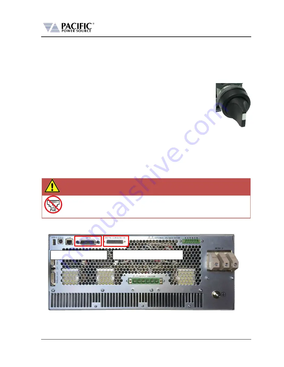
All ADF Series® models support four different remote control interface options; USB, LAN ,
RS232 and GPIB. All remote control interface connectors are located at the rear panel as
shown in the illustration below.
WARNING
Do NOT connect the RJ45 LAN (Ethernet) connector of the power source to a PoE
(Power over Ethernet) port, as the DC voltage will damage the LAN interface.
5.18.1
Rear Panel Connector Locations
Table 5-2: Remote Control Interface Connector Locations on Rear Panel ( A Versions w GPIB)
GPIB Option Connector
Auxiliary I/O DB25 Connector
Summary of Contents for 1150ADF
Page 348: ......

