

ADF SERIES® OPERATION MANUAL
SECTION 4: TECHNICAL SPECIFICATIONS
Entire Contents Copyright
2018 by Pacific Power Source, Inc. (PPS) • All Rights Reserved • No reproduction without written authorization from PPS.
ADF Series Power Source Operation Manual
Page 31 of 349
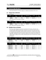
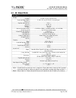
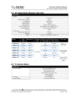
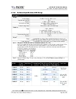
4.4
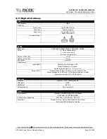
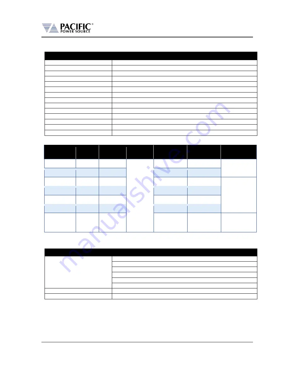
DC Output Mode (Requires Option D)
DC OUTPUT
Voltage
Range
0 – 425 Vdc
Programming Resolution
0.01 V
Accuracy
± 0.25% F.S.
Noise & Ripple
< 150 mV rms
Load Regulation
± 0.02%
Line Regulation
± 0.1% for 10% Line Change
External Voltage Sense
External Sense, max. voltage drop 5% FS.
Voltage Slew Rate
At least 3.0 V/us (DC Mode)
Isolation
750 Vdc
Current Limit
Programming Resolution
0.01 Adc
Accuracy
± 0.5 Adc
Modes
Constant Current Mode or Output Trip
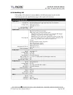
MODEL
Phase
Mode
Rated Power
DC Voltage
Range
Max. DC Current
3 Phase Mode
Max. DC Current
1 Phase Mode
Form Factor
1150ADF-xGD
1 Phase
15 kVA
0 ~ ±425 Vdc
n/a
62.5 Adc
2x 4U Chassis,
Rackmount
3150ADF- xGD
3 Phase
15 kVA
21.0 Adc
n/a
1300ADF- xGD
1 Phase
30 kVA
n/a
125.0 Adc
Fully wired 28U
Cabinet power
system
3300ADF- xGD
3 Phase
30 kVA
41.7 Adc
n/a
1450ADF- xGD
1 Phase
45 kVA
n/a
187.5 Adc
3450ADF- xGD
3 Phase
45 kVA
62.5 Adc
n/a
3600ADF- xGD
3 Phase
60 kVA
83.5 Adc
n/a
Fully wired 36U
Cabinet power
system
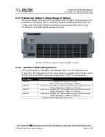
4.5
Protection Modes
PROTECTION
Protection Modes
Over Current fold-back or trip
Progr. Peak Current Limit
Power fold-back or trip
Apparent Power fold-back or trip
Over Voltage trip
Over Temperature
OVP Range
0 - 105% Vmax
AC Input Voltage
Over and Under Voltage
Summary of Contents for 1150ADF
Page 348: ......


