SECTION 6
SERVICE
Pacific Power Source ©2013
6-20
Document # 126050-10 Rev E
6.3
TROUBLESHOOTING PROCEDURE
CAUTION
-
THE SERVICE PROCEDURES OUTLINED IN THIS MANUAL ARE INTENDED FOR
USE ONLY BY PERSONNEL AUTHORIZED BY THE MANUFACTURER.
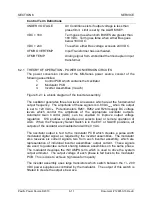
This paragraph outlines a detailed troubleshooting procedure for the MS-Series
equipment. Read and understand section 4 of this manual prior to troubleshooting.
These procedures apply to a single cabinet system or the master cabinet of a paralleled
cabinet system with all slave cabinets operating normally as a single cabinet system.
Two distinct groups of procedures are provided. They are briefly described below:
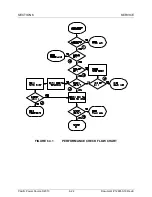
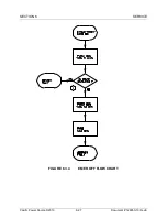
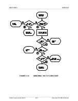
1.
Performance Check
- This procedure, figure 6.3.1, is used to verify that
the system is operating properly.
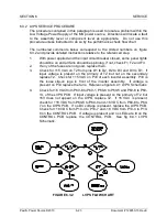
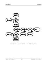
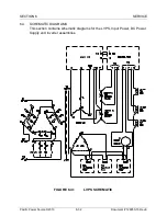
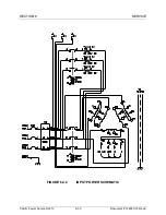
2.
Service Procedures
- These procedures, figures 6.3.2 through 6.3.6, are
used to locate and repair problems which may require removal of input
power. Do not use any of these procedures unless instructed to do so by
the performance check flow chart.
The procedures make use of flow charts along with explanatory text. This will lead the
technician to the defective component or assembly. PCB assemblies and power
assemblies are assumed to be replacement items. No attempt is made to troubleshoot
these assemblies to the component level.
WARNING
ELECTROCUTION HAZARD.
ALWAYS REMOVE ALL INPUT POWER FROM THE MAINFRAME PRIOR TO
ATTEMPTING ANY SERVICE TO THE EQUIPMENT.
LETHAL VOLTAGES ARE PRESENT INSIDE THE MAINFRAME WHEN INPUT
VOLTAGE IS APPLIED TO THE INPUT TERMINALS.
LETHAL VOLTAGES ARE PRESENT INSIDE THE MAINFRAME WHEN RED LEDS
ARE LIT ON THE DISCHARGE PCB - EVEN IF INPUT VOLTAGE IS NOT PRESENT
AT THE INPUT TERMINALS.
!


