

SECTION 6
SERVICE
Pacific Power Source ©2013
6-23
Document # 126050-10 Rev E
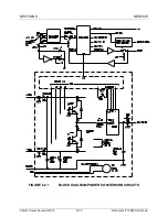
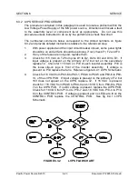
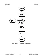
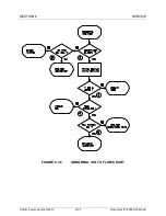
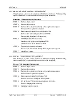
6.3.2 LVPS SERVICE PROCEDURE
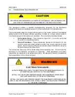
The procedure contained in this paragraph is used to locate a problem within the
Low Voltage Power Supply of the MS power source. Directions will locate a fault
to the assembly level or component level as appropriate. Do not use this
procedure unless instructed to do so by the performance check flow chart.
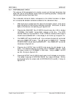
The numbered comments below correspond to the circled numbers on figure
6.3.2 and provide detailed instructions relative to the referenced step.
1.
With power applied and the input circuit breaker closed, some panel lights
should be on and all fans should be spinning, if not, check F1, F2 and F3.
2.
If any of the fuses are not good, replace them.
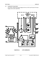
3.
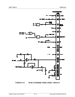
Check for 115 VAC on T2 from pins D1 to D2, D2 to D3 and D3 to D1. If
input voltage is present on the primary of T2 but not on the secondary
replace T2. Check for 115 VAC on P33 of each inverter assembly. P33 is
the loose slip-on lugs in front of the inverter assembly. If voltage is
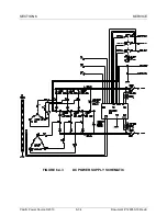
present on P33 replace the fans. Reference figure 6.4.1 LVPS Schematic.
4.
Check for 16 VAC from P60-8 to P60-1, P60-8 to P60-5 and P60-8 to P60-
13, of the LVPS PCB. If input voltage is present on the primary of T2 but
16V does not appear on the LVPS, replace T2. If 16 VAC is present,
check for +18 VDC from P60-8 to P60-9 and -18 VDC from P60-8 to P60-
7 on the LVPS PCB. If no DC voltage is present, replace the LVPS PCB.
Check for +18 VDC from P10-4 to P10-7 and -18 VDC from P10-4 to P10-
8 on the CONTROL PCB. If voltage is present and no LEDs are lit on the
CONTROL PCB replace the CONTROL PCB. See fig 6.4.1 LVPS
Schematic.
FIGURE 6.3.2
LVPS FLOW CHART


