SECTION 6
SERVICE
Pacific Power Source ©2013
6-37
Document # 126050-10 Rev E
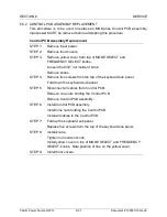
6.5.2 CONTROL PCB ASSEMBLY REPLACEMENT
This procedure is to be used to replace an MS-Series Control PCB Assembly.
Input power MUST be removed before attempting this procedure.
Control PCB Assembly Replacement
STEP 1:
Remove input power.
STEP 2:
Remove front covers.
STEP 3:
Remove yellow cover from top of MODE SELECT and
FREQUENCY SELECT knobs.
Loosen
the 9/32“ nut inside of knob.
Remove knobs.
STEP 4:
Remove five screws from the top of the keyboard sub panel.
Fold down the keyboard sub panel.
STEP 5:
Disconnect all cables from Control PCB.
Remove nine nuts holding the Control PCB.
Remove Control PCB assembly.
STEP 6:
Install Control PCB assembly.
Install nine nuts holding the Control PCB.
Install all cables to the Control PCB.
STEP 7:
Fold up the keyboard sub panel.
Replace five screws from the top of the keyboard sub panel.
STEP 8:
Install knobs.
Tighten nut inside of knob.
Install yellow cover on top of MODE SELECT and FREQUENCY
SELECT knobs. Note position of line on the yellow cover.
STEP 9:
Install front covers.

