
SECTION 6
SERVICE
Pacific Power Source ©2013
6-40
Document # 126050-10 Rev E
6.5.6 DISCHARGE PCB ASSEMBLY REPLACEMENT
This procedure is to be used to replace an MS-Series Discharge PCB Assembly.
Input power MUST be removed before attempting this procedure.
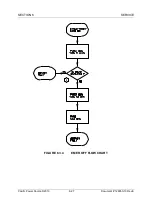
Discharge PCB Assembly Replacement
STEP 1:
Remove input power.
STEP 2:
Remove front covers.
Remove sub panels.
STEP 3:
Verify the red LEDs on the discharge PCB are off. With a DC
voltmeter verify less than 5 VDC from each Bus bar to chassis.
STEP 4:
Disconnect all cables.
Remove four nuts holding the Discharge PCB.
Remove the Discharge PCB assembly.
STEP 5:
Install Discharge PCB assembly.
Install four nuts holding the Discharge PCB.
Install all cables to the Discharge PCB.
STEP 6:
Replace sub panels.
Replace front covers.


