
SECTION 6
SERVICE
Pacific Power Source ©2013
6-44
Document # 126050-10 Rev E
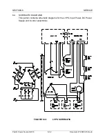
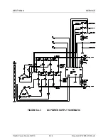
6.6.2 DC POWER SUPPLY COMPONENT REPLACEMENT
This procedure is used to replace components located on the Power Supply
Panel. Input power MUST be removed before attempting this procedure.
DC Power Supply Component Replacement
STEP 1:
Remove input power.
STEP 2:
Remove front covers and sub panels.
STEP 3:
Verify the red LEDs on the discharge PCB are off. With a DC
voltmeter verify less than 5 VDC from each Bus bar to chassis.
STEP 4:
Disconnect cables to the discharge PCB.
Disconnect output cables to the Inverters.
Remove the panel holding the discharge PCB and support it in
front of the machine.
STEP 5:
Remove Bus bars as needed.
Disconnect the AC wires as needed.
Remove screws as needed.
Remove defective component.
STEP 6:
Replace defective component.
Replace screws as needed.
Reconnect the AC wires as needed.
Replace Bus bars as needed.
STEP 7:
Reinstall the panel holding the discharge PCB.
Reconnect output cables to the Inverters.
Reconnect cables to the discharge PCB.
STEP 8:
Replace sub panels.
Replace front covers.


