
SECTION 3
INSTALLATION
Pacific Power Source ©2013
3-7
Document # 126050-10 Rev E
CHANGING INPUT VOLTAGE
1:
Verify no input power is connected.
Open Input Circuit Breaker.
2:
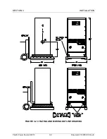
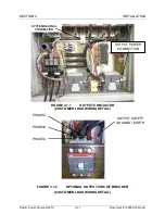
Remove front covers and sub-panels.
Remove rear panel.
3:
Remove input circuit breaker CB1.
Install new CB1 with correct amperage for new input voltage.
NOTE: Wires between CB1 and the terminal block on the Input
Power Panel must be sized appropriately for the new input power
form, see Table 3.6.1 for wire size reference.
4:
Remove input fuses F1, F2 and F3.
Install new fuses with correct amperage for new input voltage.
5:
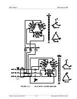
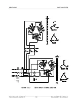
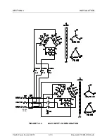
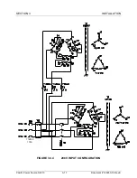
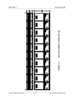
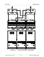
Rewire T1 and T2 per fig 3.3.1, 3.3.2, 3.3.3 or 3.3.4 as required
6:
Reinstall rear panel.
Reinstall front covers and sub-panels.
7:
Go to section 4.3.1 for first time operation.
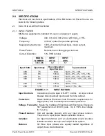
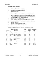
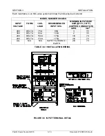
The system may be configured for any of the following input voltages:
INPUT VOLTAGE
Fig.
INPUT
CONNECT
Actual
Nominal
TAPS
TAPS
480
480
3.3.1
1,8
4-5
448
480-7%, 416+8%
3.3.1
1,8
3-5
430
480-10%, 416+3%, 400+8%
3.3.1
2,8
4-5
416
416, 400+4%, 380+10%
3.3.1
1,7
3-5
398
400, 416-4%, 380+5%
3.3.1
1,8
3-6
380
380 416-9%, 400-4%
3.3.2
2,8
4-6
366
400-9%, 380-4%
3.3.2
2,7
3-5
348
380-8%
3.3.2
2,8
3-6
240
240, 208+15%
3.3.3
1,8
1-5,4-8
208
208, 240-13%
3.3.4
1,7
1-5,3-7
190
208-9%
3.3.4
2,8
2-6,4-8


