SECTION 4
OPERATION
Pacific Power Source ©2013
4-11
Document # 126050-10 Rev E
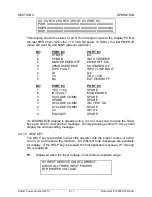
D4: PORT # 2 PORT # 3 PORT # 4 PORT # 5
PWR XXXXXXXX XXXXXXXX XXXXXXXX XXXXXXXX
EMER XXXXXXXX XXXXXXXX XXXXXXXX XXXXXXXX
NOW XXXXXXXX XXXXXXXX XXXXXXXX XXXXXXXX
This display shows the status of all of the 32 digital inputs to the Display PCB at
the last PWR down (when the + 18 VDC fell below 12.3VDC,) the last EMER off
(when Q6 went hi) and NOW (present real time.)
BIT
PORT # 2
PORT # 3
7
KYBD f3
ML
6
KYBD f4
INV OVERTEMP
5
MASTER EMER OFF
EMER OFF SW
4
XFMR OVERTEMP
SUSTAINED O/L
3
LVPS FAULT
INPUT LINE FAULT
2
LS
Q6
1
C0
VDC > 240
0
LM
EXT EMER OFF
BIT
PORT # 4
PORT # 5
7
VDC > 160
SPARE
6
INV FAULT
MOD ENABLE
5
S3 CLOSE COMM
SPARE
4
SPARE
SPARE
3
S5 CLOSE COMM
INV TEST OK
2
S7 CLOSE COMM
SPARE
1
C2
INV O/L
0
POLARITY
SPARE
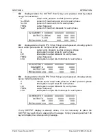
If a DIAGNOSTIC display is already active, it is not necessary to press the DIAG
key each time to view another message. Simply pressing another f1-f4 key shall
display the corresponding message.
4.3.1.5 HELP KEY
The HELP key is provided to direct the operator with the proper course of action
to turn on and operate the machine. Six different help messages are available
for display. If the HELP key is pressed the first applicable message, H1 through
H6, is displayed.
H1
Displayed when the Input Voltage is not within acceptable range.
H1: INPUT SERVICE IS NOT CORRECT.
CHECK ALL THREE INPUT PHASES
FOR PROPER VOLTAGE.

