background image

SECTION 4 


OPERATION 

Pacific Power Source ©2013 

4-20 

Document # 126050-10 Rev E
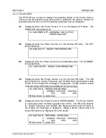
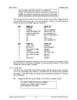
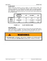
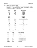
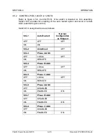
 

SLAVE STATE 

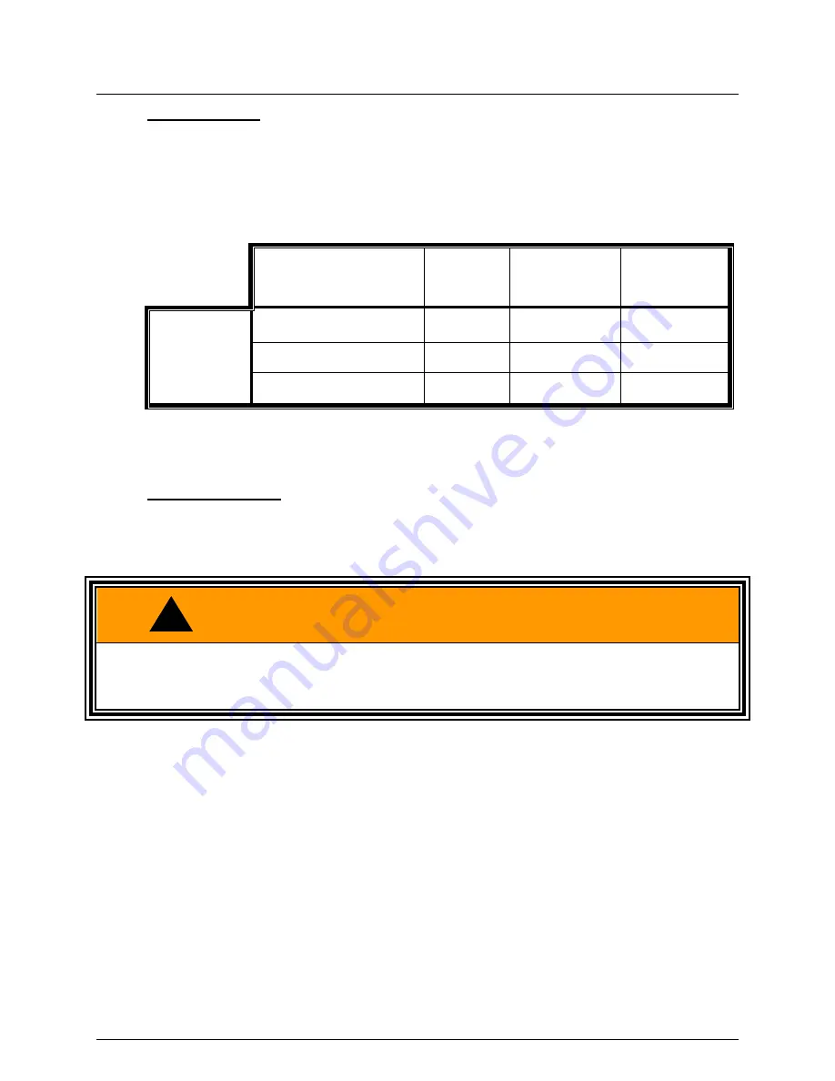
SLAVE  causes  the  machine  to  act  as  a  slave  in  a  multi  cabinet  system.  The 
machine  is  a  SLAVE  if  the  FREQUENCY  SELECT  switch  is  rotated  to  SLAVE, 
and a MASTER if in any other position. The SLAVE lamp and either EMER OFF, 
OFF, STANDBY or ON lamps shall be lit. The control mode shall be determined 
by the following table: 


MASTER 

(Mode Switch 

Position) 

OFF 

STANDBY 

ON 

SLAVE 

(Mode 

Switch 

Position) 

OFF 

OFF  

OFF 

OFF 

STANDBY 

OFF  

STANDBY 

STANDBY 

ON 

OFF  

STANDBY 

ON 


FIGURE 4.4.1 

SLAVE CONTROL MODE 


AUTO RE-START 

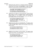
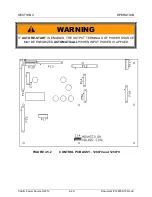
If AUTO RE-START is enabled, the Power Source shall start AUTOMATICALLY 
when  input  power  is  applied.    The  Power  Source  shall  attain  the  mode  as 
selected by the MODE SELECT switch if all internal diagnostics check out ok. 
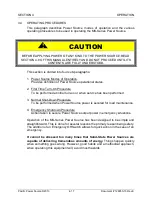
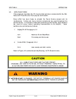
 

WARNING


IF 

AUTO RE-START

 IS ENABLED, THE OUTPUT TERMINALS OF POWER SOURCE 

MAY BE ENEGRIZED 

AUTOMATICALLY

 WHEN INPUT POWER IS APPLIED 


Summary of Contents for MS SERIES

Page 1: ...MS SERIES AC POWER SOURCE OPERATIONS MANUAL PACIFIC POWER SOURCE ...

Page 2: ...l pay all shipping charges for the repair or replacement If notice is received more than thirty 30 days from shipment all shipping charges shall be paid by the purchaser Units returned on debit memo will not be accepted and will be returned without repair This warranty is exclusive of all other warranties expressed or implied Service Spare Parts Limited Warranty Pacific Power Source PPS warrants r...

Page 3: ...HIS MANUAL IS PROPRIETARY TO PACIFIC POWER SOURCE INC THIS MANUAL MAY NOT BE COPIED OR REPRINTED WITHOUT THE EXPRESSED WRITTEN CONSENT OF PACIFIC POWER SOURCE INC PACIFIC POWER SOURCE INC 17692 FITCH IRVINE CA U S A 92614 PHONE 949 251 1800 FAX 949 756 0756 February 2013 MANUAL PART NO 126050 Revision E DWG NO 126050 10e ...

Page 4: ...THIS PAGE INTENTIONALLY BLANK ...

Page 5: ...LE 1 6 1 6 4 MULTI CABINET PARALLELED SYSTEM 1 6 2 0 SPECIFICATIONS 2 1 2 1 ELECTRICAL SPECIFICATIONS 2 1 2 1 1 INPUT POWER 2 1 2 1 2 OUTPUT POWER 2 2 2 2 MECHANICAL SPECIFICATIONS 2 3 2 3 ENVIRONMENTAL SPECIFICATIONS 2 3 3 0 INSTALLATION 3 1 3 1 PLANNING THE JOB 3 1 3 2 MOVING UNCRATING AND INSPECTION 3 4 3 3 CHANGING INPUT VOLTAGE 3 6 3 4 SETTING THE CABINET INTO PLACE 3 12 3 5 SAFETY GROUNDING ...

Page 6: ... AND START RESET SWITCHES 4 15 4 3 3 FREQUENCY SELECT SWITCH AND VOLTS ADJUST 4 16 4 3 3 1 FREQUENCY SELECT SWITCH 4 16 4 3 3 2 VOLTAGE ADJUST CONTROLS 4 16 4 4 OPERATING PROCEDURES 4 17 4 4 1 MODES OF OPERATION 4 18 4 4 2 FIRST TIME OPERATION 4 21 4 4 3 PARALLEL CABINET OPERATION 4 22 4 4 4 NORMAL SHUTDOWN PROCEDURE 4 23 4 4 5 EMERGENCY SHUTDOWN PROCEDURE 4 23 4 5 SETUP SWITCHES 4 24 4 5 1 DISPLA...

Page 7: ...3 6 3 3 DISPLAY SERVICE PROCEDURE 6 24 6 3 4 EMER OFF SERVICE PROCEDURE 6 26 6 3 5 NO INVERTER VOLTS SERVICE PROCEDURE 6 28 6 3 6 ABNORMAL VOLTAGE SERVICE PROCEDURE 6 30 6 4 SCHEMATIC DIAGRAMS 6 32 6 5 ASSEMBLY REPLACEMENT PROCEDURES 6 35 6 5 1 INVERTER ASSEMBLY REPLACEMENT 6 36 6 5 2 CONTROL PCB ASSEMBLY REPLACEMENT 6 37 6 5 3 MODULATOR PCB ASSEMBLY REPLACEMENT 6 38 6 5 4 DISPLAY PCB ASSEMBLY REP...

Page 8: ...RING DETAIL 3 17 FIGURE 3 8 1 MULTIPLE CABINET SYSTEM OUTLINE 3 19 FIGURE 3 8 2 MULTIPLE CABINET SYSTEM WIRING 3 20 FIGURE 3 9 ELECTRICAL SURVEY CHECKLIST 3 21 TABLE 4 2 INSTALLATION RECORD 4 2 FIGURE 4 3 1 LCD AND INTERROGATION SWITCHES 4 5 FIGURE 4 3 2 MODE SELECT EMER OFF AND START RESET 4 15 FIGURE 4 3 3 FREQUENCY SELECT AND VOLTS ADJUST 4 16 FIGURE 4 4 1 SLAVE CONTROL MODE 4 20 FIGURE 4 5 CAB...

Page 9: ... 19 FIGURE 6 3 1 PERFORMANCE CHECK FLOW CHART 6 22 FIGURE 6 3 2 LVPS FLOW CHART 6 23 FIGURE 6 3 3 DISPLAY FLOW CHART 6 25 FIGURE 6 3 4 EMER OFF FLOW CHART 6 27 FIGURE 6 3 5 NO INVERTER VOLTAGE FLOW CHART 6 29 FIGURE 6 3 6 ABNORMAL VOLTS FLOW CHART 6 31 FIGURE 6 4 1 LVPS SCHEMATIC 6 32 FIGURE 6 4 2 INPUT POWER SCHEMATIC 6 33 FIGURE 6 4 3 DC POWER SUPPLY SCHEMATIC 6 34 FIGURE A 1 3060 MS MAINFRAME M...

Page 10: ...f questions arise while reading this manual the user is encouraged to call Pacific Power Source Inc Pacific maintains a toll free number which is 1 800 854 2433 949 251 1800 Outside the USA Fax 949 756 0756 or contact us through our website www pacificpopwer com Section 5 discusses maintenance Section 6 is for service These sections need to be read only when such activities are required to be perf...

Page 11: ...DENTAL SHORT CIRCUIT CONDITIONS 3 DO NOT REMOVE ANY PANEL OR COVER WITHOUT FIRST REMOVING THE INPUT SERVICE BY OPENING ALL CIRCUIT BREAKERS 4 SERVICE OTHER THAN EXTERNAL CLEANING SHOULD BE REFERRED TO PERSONNEL AUTHORIZED BY THE FACTORY TO SERVICE THIS EQUIPMENT Cautions indicate a potentially hazardous situation which if not avoided may result in minor or moderate injury A caution also may be use...

Page 12: ...C power is then converted back to AC by a high frequency pulse width modulated inverter stage under the control of a highly stable digital oscillator The 3060 MS unit is designed to provide high quality output power Output regulation and total harmonic distortion are of the order of 1 at 50 or 60Hz and 2 at 400Hz Response time to a 100 step load change is 300 microseconds The machine is therefore ...

Page 13: ...rter The circuit component that contains the equipment and controls necessary to convert DC power from the rectifier to AC power required by the load A high frequency pulse width modulated switcher Internal Control System The signal processing circuits that regulate the power conversion processes detect fault conditions and control the sequence of operation of the Power Source This term may be sho...

Page 14: ...s used before the rectifier unit The transformer s winding temperature is monitored by Internal Control System diagnostics to ensure that the transformer temperature does not exceed design limits The rectifier circuit provides a soft start up feature whereby when the AC power is first applied the total initial power drawn at the input terminals will not exceed 100 of rated input power DC overvolta...

Page 15: ...S current for short circuit conditions If the short circuit is sustained the inverter will shut down and disconnect automatically from the output Each inverter output phase voltage is independently regulated to 0 5 with AGC enabled such that unbalanced loading will not cause the output voltage to exceed the specified voltage unbalance An output power filter is incorporated in the inverter unit The...

Page 16: ...80 A Nom 7 10 416 86 100 A Nom 9 4 3 8 400 91 100 A Nom 9 5 4 8 380 94 100 A Nom 5 10 4 8 17 240 150 175 A Nom 13 208 170 175 A Nom 15 9 FIGURE 2 1 1 INPUT RATINGS Input Controls Contactors provide input ON OFF control An input circuit breaker disconnects all input power from the cabinet Protection Meets National Electrical Code Protection requirements for single phase and reversed phase rotation ...

Page 17: ...tal for 400Hz Paralleled Systems maybe higher Current 175 amps per phase Inverter Fault Clearing Current Greater than 200 of full load Pulse Current Greater than 200 per phase of pulse current for driving non linear loads Inverter Overload 150 of full load for 30 seconds 125 of full load for 10 minutes 110 of full load for 1 hour Frequency Range Selectable fixed frequencies at 50 60 400 Hz Variabl...

Page 18: ... and rear 2 3 ENVIRONMENTAL SPECIFICATIONS Air Flow 1200 CFM 566 l s bottom intake top exhaust Noise level 65dbA at 3 feet Ambient Temperature Operating 0 to 40ºC Storage 10 to 70ºC Relative Humidity non condensing 0 to 80 standard configuration 0 to 95 conformal coated PCB option Elevation Operating 6500 Ft 1970 m Derate to 70 at 11 500 Ft 3480 m Storage 40 000 Ft 12 120 m Heat Dissipation at 50k...

Page 19: ...SECTION 2 SPECIFICATIONS Pacific Power Source 2013 2 4 Document 126050 10 Rev E FIGURE 2 2 OUTLINE DRAWING ...

Page 20: ...ng the system Refer to paragraph 3 2 3 Changing Input Voltage if required Refer to paragraph 3 3 4 Setting the cabinet into place Refer to paragraph 3 4 5 Making Input Connections Refer to paragraph 3 6 6 Making Output Connections Refer to paragraph 3 7 7 Multiple Cabinet Paralleled Systems Refer to paragraph 3 8 8 Inspecting the Installation Refer to paragraph 3 9 3 1 PLANNING THE JOB The main ob...

Page 21: ...ion in Figure 3 1 for planning the mechanical installation The cabinet should be placed as close as possible to the load to minimize output wiring lengths This is done to reduce distribution losses between the load and power source Shorter output wiring will provide higher quality power to the load If there is a choice between shorter power source input or output wiring choose shorter output wirin...

Page 22: ...eption Forced air intake from raised floor installations requires sealing off of the lower front and rear areas Consult factory 5 A minimum of 24 in front of the Cabinet for service 6 Altitude of installation does not exceed 6500 feet Altitudes in excess of 6500 feet require the derating of maximum operating levels 7 Relative humidity does not exceed 80 95 with conformal coat PCB option non conden...

Page 23: ...ides of the crate setting these aside for the moment Inspect all equipment for signs of damage in shipping If any damage has occurred contact the shipper and the Pacific factory for instructions If the cabinet is to be returned it must be shipped back in the original crate If no signs of damage are evident the equipment may be removed from the pallet A forklift is required to lift the cabinets off...

Page 24: ...SECTION 3 INSTALLATION Pacific Power Source 2013 3 5 Document 126050 10 Rev E FIGURE 3 2 CRATING AND MOVING OUTLINE DRAWING ...

Page 25: ...re 3 3 1 through figure 3 3 4 Each mainframe dependent upon model number will require the following Input Circuit Breaker and Fuses Input Volts CB1 F1 F2 F3 480 80 A P N 716016 1 A P N 712043 416 100 A P N 716049 1 A P N 712045 400 100 A P N 716049 1 A P N 712045 380 100 A P N 716049 1 A P N 712045 380 CE 100 A P N 716084 1 A P N 712045 240 175 A P N 716048 2 A P N 712044 208 175 A P N 716048 2 A ...

Page 26: ...2 and F3 Install new fuses with correct amperage for new input voltage 5 Rewire T1 and T2 per fig 3 3 1 3 3 2 3 3 3 or 3 3 4 as required 6 Reinstall rear panel Reinstall front covers and sub panels 7 Go to section 4 3 1 for first time operation The system may be configured for any of the following input voltages INPUT VOLTAGE Fig INPUT CONNECT Actual Nominal TAPS TAPS 480 480 3 3 1 1 8 4 5 448 480...

Page 27: ...SECTION 3 INSTALLATION Pacific Power Source 2013 3 8 Document 126050 10 Rev E FIGURE 3 3 1 480 V INPUT CONFIGURATION 716016 80A ...

Page 28: ...SECTION 3 INSTALLATION Pacific Power Source 2013 3 9 Document 126050 10 Rev E FIGURE 3 3 2 380 V INPUT CONFIGURATION 716049 100A 716084 CE ...

Page 29: ...SECTION 3 INSTALLATION Pacific Power Source 2013 3 10 Document 126050 10 Rev E FIGURE 3 3 3 240 V INPUT CONFIGURATION 716048 175A ...

Page 30: ...SECTION 3 INSTALLATION Pacific Power Source 2013 3 11 Document 126050 10 Rev E FIGURE 3 3 4 208 V INPUT CONFIGURATION 716048 175A ...

Page 31: ...R S RESPONSIBILITY TO MEET ALL APPLICABLE LOCAL AND NATIONAL CODE REQUIREMENTS WHEN INSTALLING THIS EQUIPMENT WARNING ELECTROCUTION HAZARD LETHAL VOLTAGES PRESENT AT INPUT OF MACHINE REFER CONNECTION TO A QUALIFIED ELECTRICIAN When connecting the input service certain requirements relating to safety are stated in these instructions and should be followed rigorously Input connections to the MS Seri...

Page 32: ...d currents MODEL NUMBER 3060 MS INPUT VOLTAGE FORM 100 LOAD RECOMMENDED INPUT SVC MINIMUM INPUT WIRE SIZE 75 C 167 F COPPER CONDUCTOR AWG mm2 480 DELTA 75A 80A 3 35 380 DELTA 94A 100A 2 35 240 DELTA 150A 175A 1 0 70 208 DELTA 170A 175A 2 0 70 ALL N A N A SAFETY GROUND EARTH 2 0 70 TABLE 3 6 1 INSTALLATION WIRING FIGURE 3 6 INPUT TERMINAL DETAIL ...

Page 33: ...SECTION 3 INSTALLATION Pacific Power Source 2013 3 14 Document 126050 10 Rev E FIGURE 3 6 1 CUSTOMER INPUT WIRING DETAIL CUSTOMER INPUT WIRING PHASE A B C INPUT IS NOT PHASE ROTATION SENSITIVE ...

Page 34: ... 50 175A 350A The CE option incorporates output fuses F12 F14 in the mainframe cabinet No output fuses are provided within the Cabinet in the standard configuration WARNING ELECTROCUTION HAZARD LETHAL VOLTAGES PRESENT AT OUTPUT OF MACHINE REFER CONNECTION TO A QUALIFIED ELECTRICIAN Output connections in the standard MS Series AC Power Source are made at the output contactor terminals Refer to figu...

Page 35: ...ION Pacific Power Source 2013 3 16 Document 126050 10 Rev E NOTE IT IS THE USER S RESPONSIBILITY TO MEET ALL APPLICABLE LOCAL AND NATIONAL CODE REQUIREMENTS WHEN INSTALLING THIS EQUIPMENT FIGURE 3 7 OUTPUT TERMINAL DETAIL ...

Page 36: ...Document 126050 10 Rev E FIGURE 3 7 1 OUTPUT CONTACTOR CUSTOMER LOAD WIRING DETAIL FIGURE 3 7 2 OPTIONAL OUTPUT CIRCUIT BREAKER CUSTOMER LOAD WIRING DETAIL PHASE A PHASE B PHASE C OUTPUT SAFETY GROUND EARTH SYSTEM NEUTRAL CONNECTION OUTPUT POWER CONNECTION ...

Page 37: ...necessary to operate the Multiple Cabinet System All five output wires Chassis Neutral Phase A Phase B and Phase C from each cabinet need to be paralleled Each individual output wire from each Cabinet to the output load connection MUST BE THE SAME LENGTH AND WIRE SIZE Refer to figure 3 8 2 for Multiple Cabinet System Wiring CAUTION WHEN THREE OR MORE CABINETS ARE CONNECTED IN PARALLEL A PARALLELIN...

Page 38: ...SECTION 3 INSTALLATION Pacific Power Source 2013 3 19 Document 126050 10 Rev E FIGURE 3 8 1 MULTIPLE CABINET SYSTEM OUTLINE ...

Page 39: ...SECTION 3 INSTALLATION Pacific Power Source 2013 3 20 Document 126050 10 Rev E FIGURE 3 8 2 MULTIPLE CABINET SYSTEM WIRING ...

Page 40: ... of the cabinet 2 Check input service ratings Circuit breakers and wiring to be sized in accordance with currents listed in Section 3 0 Circuit breaker time overload curves should be compatible with published curves on the Cabinet 3 Safety wiring should be sized in accordance with currents listed in Section 3 6 Ground for the Cabinet shall be connected to the Cabinet from the building ground 4 All...

Page 41: ...nections properly tightened No nicked or damaged wires etc 3 Output connections made properly Also are loads attached of the proper voltage and frequency rating The operator should refer to Section 3 0 Installation if there is any doubt regarding the above conditions 4 2 INSTALLATION RECORD During first time operation the Power Source Installation Record Table 4 2 should be completed This informat...

Page 42: ...E TABLE 4 2 INSTALLATION RECORD 1 0 Cabinet and Site Information Paragraph 4 1 4 2 Model Number Serial Number Purchase Order Work Order Modification Numbers Customer Name Technical Contact Name Title Phone Number Ext Site Address Test Technician Date Comments on Installation ...

Page 43: ... cont 2 0 Technical Record Paragraph 4 1 Parameter Phase A Phase B Phase C Input Voltage L L Input Current Output Voltage Output Current Output kVA Percent Load Output Frequency Switch Position Number Dip Switch 1 2 3 4 5 6 7 8 Control PCB S14 Display PCB S41 Display PCB S42 TABLE 4 2 INSTALLATION RECORD ...

Page 44: ...t Panel is divided into 3 basic regions 1 LCD and Interrogation Section Used to solicit Power Source parametric values Refer to paragraph 4 3 1 2 Mode Select Emer Off and Start Reset switches Used to control the operational state of the Power Source Refer to paragraph 4 3 2 3 Frequency Select and Volts Adjust Used to control the Internal Oscillator and select Master or Slave operation in Parallel ...

Page 45: ...INTERROGATION SWITCHES This paragraph provides a detailed description of each Power Source message how it is obtained and its meaning A four line 160 character display provides the communication interface between the Power Source and the operator FIGURE 4 3 1 LCD AND INTERROGATION SWITCHES ...

Page 46: ...X kW XX X XX X XX X FREQ XXX X kVA XX X XX X XX X 4 3 1 2 OUTPUT KEY The OUTPUT Key is used to display the current status of all power source output power parameters It may be pressed any time power is applied to the unit Any one of several OUTPUT displays can be seen by pressing OUTPUT and one of the function keys f1 f4 as follows O1 displayed when the OUTPUT then f1 keys are pressed showing basi...

Page 47: ...ut amps for each phase kW total system output kilowatts for each phase FREQ output frequency kVA total system output kilo Volt Amps for each phase O3 SYSTEM V XXX XXX XXX XXX XXX XXX SUMMARY A XXXX XXXX XXXX OUTPUT kW XXX XXX XXX FREQ XXX X kVA XXX XXX XXX O4 displayed when the OUTPUT then f4 keys are depressed showing remote sense metering parameters V remote sense output volts phase to neutral p...

Page 48: ... Standby state The STANDBY lamp shall be lit S3 CAB IS STBY READY FOR OPERATION S4 Displayed when the Power Source is in the Normal ON state The ON lamp shall be lit Output Frequency and LOAD the highest percent load shown in the Output O2 message is displayed Single Cabinet output volts and amps information are displayed for each phase S4 CAB IS ON OPERATION NORMAL V XXX XXX XXX XXX XXX XXX A XXX...

Page 49: ...XXX XXX XXX XXX XXX XXX A XXX XXX XXX FREQ XXX X LOAD XXX S8 Displayed when the Power Source is in an Alarm condition caused by an OUTPUT OVER VOLTAGE S8 CAB IS ON WARNING OVER VOLTAGE V XXX XXX XXX XXX XXX XXX A XXX XXX XXX FREQ XXX X LOAD XXX S9 Displayed when the Power Source is in an Alarm condition caused by an OUTPUT UNDER FREQUENCY S9 CAB IS ON WARNING UNDER FREQUENCY V XXX XXX XXX XXX XXX ...

Page 50: ...NCY OFF OR D1 DIAGNOSTIC EMERGENCY OFF CAUSED BY MASTER EMERGENCY OFF SUSTAINED OVERLOAD INVERTER FAULT EMER OFF BUTTON TRANSFORMER OVERTEMP INVERTER OVERTEMP LVPS FAULT Bus VOLTAGE 240 VDC EXTERNAL EMERGENCY OFF NO MASTER ON LINE When the DIAG then f2 keys are pressed the input transformer temperature in degrees C and inverter temperature status OK Not OK are displayed D2 DIAGNOSTIC TEMPERATURE D...

Page 51: ... EXT EMER OFF BIT PORT 4 PORT 5 7 VDC 160 SPARE 6 INV FAULT MOD ENABLE 5 S3 CLOSE COMM SPARE 4 SPARE SPARE 3 S5 CLOSE COMM INV TEST OK 2 S7 CLOSE COMM SPARE 1 C2 INV O L 0 POLARITY SPARE If a DIAGNOSTIC display is already active it is not necessary to press the DIAG key each time to view another message Simply pressing another f1 f4 key shall display the corresponding message 4 3 1 5 HELP KEY The ...

Page 52: ... STANDBY position and pressing the START RESET button This will charge up the internal high voltage dc power supplies and start the inverter operating H3 SYSTEM IS IN NORMAL OFF STATE TO PLACE IN STANDBY ROTATE THE MODE SELECT SWITCH TO STANDBY AND PRESS START RESET H4 Displayed when the cabinet is in the Standby State The cabinet is ready to deliver output power but the output contactor is open I...

Page 53: ...nd DISABLED display text changes accordingly A1 ALARM DISABLED PRESS f1 OV XXX AND HOLD ALARM TO ENABLE f2 UV XXX USE f1 f2 f3 f4 BUTTONS f3 OF XXX TO CHANGE LIMITS f4 UF XXX Whenever message A1 is displayed limits are subject to change by use of f1 through f4 buttons First press and hold of f1 causes OV to increase at about 5 volts per second Second press and hold causes OV to decrease at about 5...

Page 54: ...rol of the cabinet is through the MODE SELECT switch The design of the switch is such that only one Mode Position can occur at any time The three available switch positions are defined as follows OFF The cabinet is shut off No power is supplied to the load A red LED next to the OFF position is lighted when there is no power applied to the output and diagnostic checks are OK STANDBY The cabinet is ...

Page 55: ...tch is then required before the cabinet can be brought back on line Two off lamps are used to indicate the Off states The Emergency Off state is indicated by a lamp that illuminates the EMER OFF push button A lamp next to the OFF text on the Mode Select switch indicates that the cabinet is in the Normal Off State The Normal Off state lamp is inhibited from being ON when an EMERGENCY OFF condition ...

Page 56: ...ernal oscillator VAR This is a 47 to 500 Hz variable frequency control for the internal oscillator EXT This selects an external oscillator input for the Power Source SLAVE In this position this cabinet is a SLAVE to another master in a Multiple Cabinet System One and only one cabinet may be MASTER in a Multiple Cabinet System The MASTER Frequency shall control the entire Multiple Cabinet System 4 ...

Page 57: ...erformed at initial turn on or when service has been performed 3 Normal Shut Down Procedure To be performed when Power Source power is secured for load maintenance 4 Emergency Shutdown Procedure Action taken to secure Power Source output power in emergency situations Operation of the MS Series Power Source has been designed to be simple and straightforward This is done for several reasons the prim...

Page 58: ... except for the low voltage power supply OFF shall be achieved if the following are true A The EMER OFF lamp is off B The OFF lamp is on C The STANDBY lamp is off D The ON lamp is off STANDBY STATE STANDBY is when the input contactor is closed and the machine is ready to deliver power to a load but the output contactor is open The STANDBY lamp is on Observe the following start sequence to achieve ...

Page 59: ... voltage power supply The EMER OFF push button shall be lit The following shall cause an EMER OFF A EMER OFF BUTTON the EMER OFF push button has been pressed B MASTER EMERGENCY OFF The Master Cabinet is in an EMERGENCY OFF STATE and this machine is a SLAVE C INPUT LINE FAULT the input power is not within limits D LVPS FAULT one of the low voltage power supplies has failed E BUS VOLTAGE 240 VDC one...

Page 60: ... be determined by the following table MASTER Mode Switch Position OFF STANDBY ON SLAVE Mode Switch Position OFF OFF OFF OFF STANDBY OFF STANDBY STANDBY ON OFF STANDBY ON FIGURE 4 4 1 SLAVE CONTROL MODE AUTO RE START If AUTO RE START is enabled the Power Source shall start AUTOMATICALLY when input power is applied The Power Source shall attain the mode as selected by the MODE SELECT switch if all i...

Page 61: ...oceed Rotate the Mode Select Switch to OFF and press START RESET The EMER OFF indicator will go out STEP 5 Place the cabinet in the STANDBY state by rotating the Mode Select Switch to STANDBY and pressing the START RESET button The STANDBY lamp will illuminate The high voltage power supplies are now energized and the inverters are producing voltage The output contactor is open Cabinet output volta...

Page 62: ...ves Disconnect any load from the output of the system Close all of the Circuit Breakers at the Output Load Center Press OUTPUT then f1 keys on all Cabinets in the system to monitor each Cabinet s output voltages and currents STEP 6 On the MASTER turn the Volts Adjust down to 0 VAC Rotate the MODE SELECT to ON and press START RESET Select one and only one SLAVE Rotate its MODE SELECT to ON and pres...

Page 63: ...l loads and open output circuit breaker if provided STEP 2 Rotate the Mode Select Switch to the OFF position STEP 3 Open the input power circuit breaker This removes all power to and from the cabinet 4 4 5 EMERGENCY SHUTDOWN PROCEDURE Emergency shutdown is accomplished by depressing the EMER OFF Switch at any time The principle function of the Emergency Off state is to open the input and output co...

Page 64: ... switches are used to convey certain operating characteristics to the cabinet These switches are summarized as follows 1 Display PCB Paragraph 4 5 1 S41 Machine ID and Baud Rate S42 For testing and future use 2 Control PCB Paragraph 4 5 2 S14 Auto restart and AGC control Refer to Figure 4 5 Cabinet Assembly Drawing for PC Board location CAUTION ALL CABINET SWITCHES ARE FACTORY PRESET CHANGING ANY ...

Page 65: ...SECTION 4 OPERATION Pacific Power Source 2013 4 25 Document 126050 10 Rev E FIGURE 4 5 CABINET ASSEMBLY ...

Page 66: ... 5kVA OFF ON Undefined ON OFF Undefined ON ON Undefined S41 3 Undefined S41 4 Undefined S41 5 S41 6 Serial Port A Baud Rate OFF OFF 300 OFF ON 1200 ON OFF 2400 ON ON 9600 S41 7 S41 8 Serial Port B Baud Rate OFF OFF 300 OFF ON 1200 ON OFF 2400 ON ON 9600 Normal Shipping Configuration is as follows S41 1 OFF 62 5kVA Machine S41 2 OFF 62 5kVA Machine S41 3 OFF Undefined S41 4 OFF Undefined S41 5 OFF ...

Page 67: ...SECTION 4 OPERATION Pacific Power Source 2013 4 27 Document 126050 10 Rev E FIGURE 4 5 1a DISPLAY PCB ASSY 126072 FIGURE 4 5 1b DISPLAY PCB ASSY 126172 ...

Page 68: ...ption and local or remote AGC automatic gain control Switch S14 assignments are as follows S14 1 Auto Restart Normal Configuration as Shipped OFF OFF OFF ON ON S14 2 Undefined OFF S14 3 Phase A AGC OFF LOCAL OFF ON REMOTE S14 4 Phase B AGC OFF LOCAL OFF ON REMOTE S14 5 Phase C AGC OFF LOCAL OFF ON REMOTE S14 6 Phase A AGC OFF DISABLED ON ENABLED ON S14 7 Phase B AGC OFF DISABLED ON ENABLED ON S14 ...

Page 69: ... Power Source 2013 4 29 Document 126050 10 Rev E WARNING IF AUTO RE START IS ENABLED THE OUTPUT TERMINALS OF POWER SOURCE MAY BE ENEGRIZED AUTOMATICALLY WHEN INPUT POWER IS APPLIED FIGURE 4 5 2 CONTROL PCB ASSY 126070 and 126079 ...

Page 70: ...4 6 for location of these connectors 4 6 1 P1 P2 PARALLELING These are used for Paralleling cabinets in multiple cabinet systems They are DB25P type Pin numbers are as follows Pin Description 1 ØA Error Signal 2 ØB Error Signal 3 ØC Error Signal 4 Common Error Signal 5 Triangle Wave Sync 6 Master on line 7 Remote mode 0 8 Remote mode 2 9 Remote Emer Off 10 Remote Start 11 ØA System Amps 12 ØB Syst...

Page 71: ...SECTION 4 OPERATION Pacific Power Source 2013 4 31 Document 126050 10 Rev E FIGURE 4 6 CABINET TOP VIEW FEATURE CONNECTOR DETAIL ...

Page 72: ... such as a dumb terminal or PC set up as a DTE J4 or COM B is a DTE port configured to be interfaced with a DCE device such as a modem A female DB 25 socket is also provided for this port BAUD RATE The Baud Rates for data transmission are 300 1200 2400 or 9600 as selected by switch S41 on the Display PCB Assembly Refer to Figure 4 5 1 COMMUNICATION DATA FORMAT Data is transferred as an 8 bit word ...

Page 73: ...OM B 4 RTSB REQUEST TO SEND PORT B 20 DTRB DATA TERMINAL READY PORT B 2 TXDB TRANSMIT DATA PORT B 3 RXDB RECEIVE DATA PORT B 8 DCDB DATA CARRIER DETECT PORT B 5 CTSB CLEAR TO SEND PORT B 7 GRD GROUND TABLE 4 6 2 SERIAL I O CONNECTIONS With the serial port it is possible to obtain all Front Panel Display information described in section 4 3 1 This paragraph provides the syntax and a brief descripti...

Page 74: ...ak Current kVA kW Frequency O3 RET Output Screen 3 SYSTEM VLN VLL Amps kW kVA Frequency O4 RET Output Screen 4 REMOTE VLN VLL Amps kW kVA Frequency S RET Status Screen Varies D1 RET Diag Screen 1 Cause of Emergency Off D2 RET Diag Screen 2 Temperature Data D3 RET Diag Screen 3 Internal Voltages D4 RET Diag Screen 4 Binary Ports 2 5 H RET Help Screen Varies ST RET Reset Display CPU Same as pressing...

Page 75: ... Gnd 4 6 4 J5 AND J7 SYSTEM METERING OUTPUTS J5 is a System Volts output signal connector System Volts are divided down by 25 to 1 and sent to this connector This connector is a DA15S type Example 120 VAC 60 Hz at the output contactor equals 4 80 VAC 60 Hz at J5 Pin Numbers are as follows 1 Phase A System Volts Output 11 Phase B System Volts Output 8 Phase C System Volts Output 2 7 12 Gnd J7 is a ...

Page 76: ...t 5 Phase B Remote Amps Input 6 Phase C Remote Amps Input 7 Neut Remote Amps Input 8 Gnd 4 6 6 J9 AUXILIARY ALARM OUTPUTS This connector alerts the user to conditions that cause alarm status in the cabinet These are digital 0 to 5 VDC outputs designed to operate small relays which the user may utilize to operate remote lights and buzzers This connector is a DA15S type Pin Numbers are as follows 1 ...

Page 77: ... 1 3 The following procedure is recommended to be performed at 3 month intervals STEP 1 Record cabinet input data by pressing the INPUT key on the front panel display STEP 2 Record cabinet output data by pressing the OUTPUT then f1 and f2 keys on the front panel display STEP 3 Record the current Status message by pressing the STATUS key on the front panel display STEP 4 Record Diagnostic messages ...

Page 78: ...SECTION 5 SERVICE Pacific Power Source 2013 5 2 Document 126050 10 Rev E FIGURE 5 1 1 REAR OF MS SERIES CABINET BACK PANEL REMOVED FIGURE 5 1 2 UNDERSIDE OF MS SERIES INVERTERS ...

Page 79: ... The following procedure is recommended to be performed at 4 to 6 week intervals STEP 1 Clean the flame baffle underneath the bottom of the MS using a vacuum cleaner with a brush attachment TABLE 5 1 2 4 6 WEEK MAINTENANCE CYCLE FIGURE 5 1 3 FIRESCREEN LOCATION FOR CLEANING ...

Page 80: ... LOG EQUIPMENT MODEL NO EQUIPMENT SERIAL NO DATE TECHNICIAN 1 CABINET DATA I1 INPUT V NORMAL A kW FREQ kVA O1 CABINET V OUTPUT A EFF kW FREQ KVA O2 CABINET V OUTPUT I PEAK kVA FREQ kW O3 SYSTEM V SUMMARY A OUTPUT KW FREQ KVA O4 REMOTE V OUTPUT A KW FREQ KVA FIGURE 5 1 4 MS SERIES MAINTENANCE LOG ...

Page 81: ... E MS SERIES MAINTENANCE LOG cont 2 STATUS INFORMATION S CAB 3 DIAGNOSTIC INFORMATION D1 DIAGNOSTIC D2 DIAGNOSTIC TEMPERATURE DATA XFMR DEG C INV DEG C D3 DIAGNOSTIC INTERNAL VOLTAGES BUS LVPS VDC VDC VDC VDC D4 Port 2 Port 3 Port 4 Port 5 PWR EMER NOW COMMENTS APPEARANCE ...

Page 82: ...anized as follows Paragraph 6 1 Provides a brief description of each assembly Paragraph 6 2 Provides the theory of operation required to troubleshoot the system Paragraph 6 3 Provides step by step troubleshooting procedures Paragraph 6 4 This section contains schematic diagrams for the LVPS Input Power DC Power Supply and Inverter assemblies Paragraph 6 5 Provides procedures for replacing defectiv...

Page 83: ...to low voltages which are required for the control and display PCB s With the CE Option a High Voltage DC blocking PCB Assembly P N 126370 is mounted with the Discharge PCB Assembly 4 COMPONENTS R4 and R5 Discharge Resistors P N 769990 056 S3 Input Contactor P N 717067 S7 Slow Start Input Contactor P N 717005 CB1 Input Circuit Breaker 480 VAC Input 80A P N 716016 380 VAC Input 100A STD P N 716049 ...

Page 84: ...SECTION 6 SERVICE Pacific Power Source 2013 6 3 Document 126050 10 Rev E FIGURE 6 1 1 MAINFRAME ...

Page 85: ...cillator output is a digitally synthesized sine wave 2 MODULATOR PCB ASSEMBLY P N 126071 This circuit assembly receives the output of the oscillator and produces the pulse width modulated signals required to drive the inverter assemblies 3 DISPLAY PCB ASSEMBLY P N 126072 or 126172 This circuit assembly is mounted to the front panel and contains a CPU which drives an LCD for metering status diagnos...

Page 86: ...SECTION 6 SERVICE Pacific Power Source 2013 6 5 Document 126050 10 Rev E FIGURE 6 1 2 CONTROL MODULE ...

Page 87: ...DC to AC and drives the output The inverter assembly is housed in a metal case This inverter assembly has been designed to reduce RFI EMI 2 DRIVER PCB ASSEMBLY P N 126270 This PCB assembly receives control signals from the modulator provides isolation and then drives the power transistors This PCB is a subassembly of the inverter assembly 3 SNUBBER PCB ASSEMBLY P N 126272 This PCB assembly is used...

Page 88: ...SECTION 6 SERVICE Pacific Power Source 2013 6 7 Document 126050 10 Rev E FIGURE 6 1 3 INVERTER side view with covers removed ...

Page 89: ...are pressed the status inputs to the Display PCB are displayed Reference section 4 3 1 4 This display may be used to determine the state of control terms in the system Control Terms are defined as follows Control Term Definitions 3 PHASE PRESENT True when all three input phases are present AGC Automatic Gain Control Improves steady state regulation of the output voltage AUTO RESTART PULSE Same as ...

Page 90: ...tely 30 kHz and no fuses are blown Does not test the quality of the sine wave being produced and does not care if inverter is in current limit INV VOLTS Inverter output voltage Inverter side of the output contactor INV AMPS Inverter output amps INV O L Inverter is in current limit LM Local Master the FREQUENCY SELECT switch is not in the SLAVE position LS Local Slave the FREQUENCY SELECT switch is...

Page 91: ...d to regulate to this point REMOTE START True if the master is starting REMOTE AMPS Remote amps from remote current transformers S3 CLOSE COMM S5 CLOSE COMM S7 CLOSE COMM Drive signal which causes the relay to close SLAVE LAMP Is lit whenever the FREQUENCY SELECT switch is in the SLAVE position STANDBY LAMP Is lit if S3 CLOSE COMM or S7 CLOSE COMM is true and S5 CLOSE COMM is false START RESET SW ...

Page 92: ...tiometers R261 R262 and R263 supply DC voltage levels which control the amplitude of the appropriate oscillator outputs Automatic Gain Control AGC can be enabled to improve output voltage regulation S14 enables or disables and selects local or remote operation of AGC When the Frequency Select Switch is in the EXT or SLAVE positions all outputs of the oscillator are disabled and will be 0 VAC The o...

Page 93: ...SECTION 6 SERVICE Pacific Power Source 2013 6 12 Document 126050 10 Rev E FIGURE 6 2 1 BLOCK DIAGRAM POWER CONVERSION CIRCUITS ...

Page 94: ...ressing the START RESET push button will allow normal operation Rotating the MODE SELECT switch to STANDBY and then pressing START RESET will turn on S7 the Slow Turn On Contactor Resistors R1 R2 and R3 limit the inrush current during transformer turn on and charging of the power supply capacitors At this point the MODULATOR ENABLE signal is high allowing the inverter to create sine waves at the o...

Page 95: ...SECTION 6 SERVICE Pacific Power Source 2013 6 14 Document 126050 10 Rev E FIGURE 6 2 2 BLOCK DIAGRAM SYSTEM CONTROL CIRCUITS ...

Page 96: ...el assembly which contains the rectifiers capacitors and DC fuses make up the main DC Power Supply Circuits The main DC Power Supply is a bipolar supply which produces 200 VDC This supply is an unregulated supply It is actually two independent 200 VDC supplies which are stacked on top of each other The rectifiers are configured as two full wave three phase bridges These two bridges are connected a...

Page 97: ...SECTION 6 SERVICE Pacific Power Source 2013 6 16 Document 126050 10 Rev E FIGURE 6 2 3 BLOCK DIAGRAM DC POWER SUPPLY ...

Page 98: ... assembly contains the resistor voltage dividers to scale down system voltages to a low level These system voltages are sent to the Control PCB The Control PCB provides all input signals analog and digital except input amps to the Display PCB CT11 CT13 provide the input current terms required by the Display PCB Figure 6 2 4 is the block diagram for the meter and display portion of the MS Series po...

Page 99: ... of the paralleled system P1 and P2 are the paralleling connectors Tying pin 18 and pin 19 together with isolated external contacts shall cause an external emergency off of the system If a cabinet is a Master and in an EMER OFF state it will cause all paralleled cabinets to be in an EMER OFF state The master EMER OFF must be cleared first then any slave EMER OFF may be cleared When all slave cabin...

Page 100: ...SECTION 6 SERVICE Pacific Power Source 2013 6 19 Document 126050 10 Rev E FIGURE 6 2 5 BLOCK DIAGRAM PARALLELING CIRCUITS ...

Page 101: ... operating properly 2 Service Procedures These procedures figures 6 3 2 through 6 3 6 are used to locate and repair problems which may require removal of input power Do not use any of these procedures unless instructed to do so by the performance check flow chart The procedures make use of flow charts along with explanatory text This will lead the technician to the defective component or assembly ...

Page 102: ...LCD to display INTERNAL VOLTAGES Ignore BUS voltages at this time The LVPS shall be between 15 and 20 VDC If the LVPS was outside of this range it would cause an EMER OFF If the display is not correct go to figure 6 3 3 3 The EMER OFF lamp should be off If you suspect the lamp it s self is bad press the EMER OFF button This will cause an EMER OFF Pressing START RESET should clear the EMER OFF If a...

Page 103: ...SECTION 6 SERVICE Pacific Power Source 2013 6 22 Document 126050 10 Rev E FIGURE 6 3 1 PERFORMANCE CHECK FLOW CHART ...

Page 104: ... replace them 3 Check for 115 VAC on T2 from pins D1 to D2 D2 to D3 and D3 to D1 If input voltage is present on the primary of T2 but not on the secondary replace T2 Check for 115 VAC on P33 of each inverter assembly P33 is the loose slip on lugs in front of the inverter assembly If voltage is present on P33 replace the fans Reference figure 6 4 1 LVPS Schematic 4 Check for 16 VAC from P60 8 to P6...

Page 105: ...detailed instructions relative to the referenced step 1 Reset the Display PCB by simultaneously pressing INPUT OUTPUT and HELP keys If this does not cause a reset remove input power from the machine and reapply input power If this does not reset the Display PCB replace the Display PCB 2 Pressing the DIAG KEY then f3 KEYS shall cause the LCD to display INTERNAL VOLTAGES Ignore BUS voltages at this ...

Page 106: ...SECTION 6 SERVICE Pacific Power Source 2013 6 25 Document 126050 10 Rev E FIGURE 6 3 3 DISPLAY FLOW CHART ...

Page 107: ...verload condition for an extended period of time and shut off Press the OUTPUT then f2 KEYS to display the system load in percentages I PEAK kVA and kW If any of the six fields are greater than 100 the machine is overloaded INPUT LINE FAULT input voltage is wrong Ref 4 3 1 1 Correct the input voltage INVERTER FAULT inverter or modulator PCB failure If F10 or F11 are open power transistors in the I...

Page 108: ...SECTION 6 SERVICE Pacific Power Source 2013 6 27 Document 126050 10 Rev E FIGURE 6 3 4 EMER OFF FLOW CHART ...

Page 109: ...Input Transformer and wiring Reference figure 6 4 2 Input Power Schematic and figure 6 4 3 DC Power Supply Schematic 4 If the Input Contactor S3 is open try to close it Rotate the MODE SELECT to STANDBY and press START RESET This should cause the Slow Turn on Contactor S7 to close for one second The Input Contactor S3 should close before the Slow Turn on Contactor S7 opens Check for 115 VAC on the...

Page 110: ...SECTION 6 SERVICE Pacific Power Source 2013 6 29 Document 126050 10 Rev E FIGURE 6 3 5 NO INVERTER VOLTAGE FLOW CHART ...

Page 111: ...sed check for 115 VAC on the coil If 115 VAC is present on the coil and the contactor does not close replace the contactor If no voltage is present on the coil and the ON lamp is on check the wiring or replace control PCB Reference figure 6 4 1 LVPS Schematic 3 Pressing the OUTPUT then f2 KEYS displays the system load in percentages I PEAK kVA and kW Verify that the machine is not overloaded all s...

Page 112: ...SECTION 6 SERVICE Pacific Power Source 2013 6 31 Document 126050 10 Rev E FIGURE 6 3 6 ABNORMAL VOLTS FLOW CHART ...

Page 113: ...ICE Pacific Power Source 2013 6 32 Document 126050 10 Rev E 6 4 SCHEMATIC DIAGRAMS This section contains schematic diagrams for the LVPS Input Power DC Power Supply and Inverter assemblies FIGURE 6 4 1 LVPS SCHEMATIC ...

Page 114: ...SECTION 6 SERVICE Pacific Power Source 2013 6 33 Document 126050 10 Rev E FIGURE 6 4 2 INPUT POWER SCHEMATIC ...

Page 115: ...SECTION 6 SERVICE Pacific Power Source 2013 6 34 Document 126050 10 Rev E FIGURE 6 4 3 DC POWER SUPPLY SCHEMATIC ...

Page 116: ...IS MANUAL ARE INTENDED FOR USE ONLY BY PERSONNEL AUTHORIZED BY THE MANUFACTURER WARNING ELECTROCUTION HAZARD ALWAYS REMOVE ALL INPUT POWER FROM THE MAINFRAME PRIOR TO ATTEMPTING ANY SERVICE TO THE EQUIPMENT LETHAL VOLTAGES ARE PRESENT INSIDE THE MAINFRAME WHEN INPUT VOLTAGE IS APPLIED TO THE INPUT TERMINALS LETHAL VOLTAGES ARE PRESENT INSIDE THE MAINFRAME ON THE DC BUS WHEN RED LEDS ARE LIT ON THE...

Page 117: ...ove Bus bars from the front of the inverters Be careful not to spin the studs Disconnect P33 the fan wires and push them up into the control box Remove three screws at the bottom of the Inverter assembly Slide Inverter assembly out of mainframe STEP 6 Slide Inverter assembly into mainframe Reinstall three screws at the bottom of the Inverter assembly STEP 7 Replace Bus bars on the front of the inv...

Page 118: ...de of knob Remove knobs STEP 4 Remove five screws from the top of the keyboard sub panel Fold down the keyboard sub panel STEP 5 Disconnect all cables from Control PCB Remove nine nuts holding the Control PCB Remove Control PCB assembly STEP 6 Install Control PCB assembly Install nine nuts holding the Control PCB Install all cables to the Control PCB STEP 7 Fold up the keyboard sub panel Replace f...

Page 119: ...tor PCB assembly Install the nuts holding the Modulator PCB Install all cables to the Modulator PCB STEP 6 Fold up the keyboard sub panel Replace five screws from the top of the keyboard sub panel STEP 7 Install front covers 6 5 4 DISPLAY PCB ASSEMBLY REPLACEMENT This procedure is to be used to replace an MS Series Display PCB Assembly Input power MUST be removed before attempting this procedure D...

Page 120: ...an MS Series LVPS PCB Assembly Input power MUST be removed before attempting this procedure LVPS PCB Assembly Replacement STEP 1 Remove input power STEP 2 Remove front covers STEP 3 Remove five screws from the top of the keyboard sub panel Fold down the keyboard sub panel STEP 4 Disconnect all cables from the LVPS PCB Remove four nuts holding the LVPS PCB Remove the LVPS PCB assembly STEP 5 Instal...

Page 121: ...acement STEP 1 Remove input power STEP 2 Remove front covers Remove sub panels STEP 3 Verify the red LEDs on the discharge PCB are off With a DC voltmeter verify less than 5 VDC from each Bus bar to chassis STEP 4 Disconnect all cables Remove four nuts holding the Discharge PCB Remove the Discharge PCB assembly STEP 5 Install Discharge PCB assembly Install four nuts holding the Discharge PCB Insta...

Page 122: ...s Remove top screen and side covers STEP 3 Disconnect all cables Remove six nuts holding the Driver PCB Remove the Driver PCB assembly STEP 4 Install Driver PCB assembly Install six nuts holding the Driver PCB Install all cables to the Driver PCB STEP 5 Install top screen and side covers Install all screws holding the top screen and side covers STEP 6 Install the Inverter assembly as described in ...

Page 123: ...ur nuts holding the Snubber PCB Remove the Snubber PCB assembly STEP 4 Install Snubber PCB assembly Install four nuts holding the Snubber PCB Solder resistor wires to the Snubber PCB STEP 5 Install top screen and side covers Install all screws holding the top screen and side covers STEP 6 Install the Inverter assembly as described in section 6 5 1 6 6 COMPONENT REPLACEMENT PROCEDURES This procedur...

Page 124: ... it in front of the machine STEP 5 Disconnect the AC wires as needed Remove screws as needed Remove defective component STEP 6 Replace defective component Replace screws as needed Reconnect the AC wires as needed STEP 7 Reinstall the panel holding CB1 STEP 8 Replace sub panels and front covers WARNING ELECTROCUTION HAZARD ALWAYS REMOVE ALL INPUT POWER FROM THE MAINFRAME PRIOR TO ATTEMPTING ANY SER...

Page 125: ...r verify less than 5 VDC from each Bus bar to chassis STEP 4 Disconnect cables to the discharge PCB Disconnect output cables to the Inverters Remove the panel holding the discharge PCB and support it in front of the machine STEP 5 Remove Bus bars as needed Disconnect the AC wires as needed Remove screws as needed Remove defective component STEP 6 Replace defective component Replace screws as neede...

Page 126: ...r PCB assembly if needed as described in section 6 5 8 STEP 4 Disconnect wires as needed Remove screws as needed Remove defective component STEP 5 Replace defective component Replace screws as needed Reconnect wires as needed STEP 6 Install the Snubber PCB assembly if needed as described in section 6 5 8 STEP 7 Install top screen and side covers Install all screws holding the top screen and side c...

Page 127: ...e name and phone number of an individual that can be contacted and the RMA number 3 Attach the mainframe serial number from which the assembly came from and a description of the service required 4 Pack the equipment in the original carton or crate if available PACK CAREFULLY TO AVOID EQUIPMENT DAMAGE IN TRANSIT PACIFIC POWER SOURCE CORPORATION SHALL NOT BE RESPONSIBLE FOR REPAIR OF DAMAGE DUE TO I...

Page 128: ...4 B1 21 TERMINAL BLOCK 3 TERMINAL PRESSURE 300A 1 705011 TB1 22 TERMINAL BD 6 TERMINAL DOUBLE ROW 30A 1 705046 TB2 23 SWITCH SPDT MOMENTARY ILLUM 0 75SQ 2 710023 S12 13 24 FUSE 1A 500VDC 13 32 X 1 480 VAC INPUT STD 3 712043 F1 3 FUSE 1 5A 500VDC 13 32 X 1 380 VAC INPUT CE OPTION 3 712045 F1 3 FUSE 2A 500VDC 13 32 X 1 240 208 VAC INPUT OPTION 3 712044 F1 3 25 CKT BKR 3POLE 80A 480VAC CODE U 480VAC ...

Page 129: ...120VAC COIL 1 717067 S3 49 CKT BKR 3POLE 175A 230VAC CODE U 1 716048 CB2 OPTIONAL OUTPUT NOTE QUANTITIES IN BRACKETS ARE FOR OPTIONAL INPUT VOLTAGE AND OUTPUT BREAKER CONFIGURATIONS REFER TO THE SETUP AND INSTALLATION SECTIONS FOR MORE INFORMATION FIGURE A 2 3060 MS INVERTER ASSEMBLY MAINTENANCE SERVICEABLE PARTS ITEM DESCRIPTION QTY P N CKT SYMBOL 1 INDUCTOR 250uH 16ARMS 12 530014 L1 12 2 FAN 6 7...

Page 130: ...APPENDIX B SYSTEM SCHEMATIC Pacific Power Source 2013 B 1 Document 126050 10 Rev E FIGURE B 1 3060 MS SYSTEM SCHEMATIC ...

Reviews: