

SECTION 4
OPERATION
Pacific Power Source ©2013
4-24
Document # 126050-10 Rev E
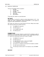
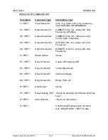
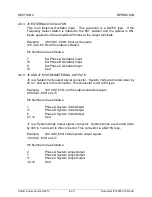
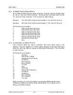
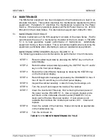
4.5
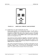
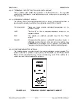
SETUP SWITCHES
This paragraph describes the PC mounted dip switches contained within the MS-
Series AC Power Source, their purpose and location.
Every effort has been made to simplify the Power Source design and its
maintenance. To this end, many common components are used throughout the
product family. To maintain commonality within the product family, logic switches
are used to convey certain operating characteristics to the cabinet. These
switches are summarized as follows:
1.
Display PCB, Paragraph 4.5.1
S41:
Machine ID and Baud Rate
S42:
For testing and future use.
2.
Control PCB, Paragraph 4.5.2
S14:
Auto restart and AGC control.
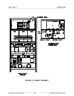
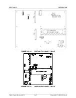
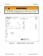
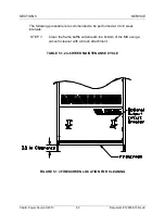
Refer to Figure 4.5, Cabinet Assembly Drawing, for PC Board location.
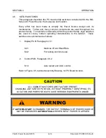
CAUTION
ALL CABINET SWITCHES ARE FACTORY PRESET.
CHANGING ANY SWITCH POSITION, WITHOUT PROPERLY IDENTIFYING ITS
LOCATION AND PURPOSE, MAY CAUSE SERIOUS EQUIPMENT DAMAGE.
WARNING
IF
AUTO RE-START
IS ENABLED, THE OUTPUT TERMINALS OF POWER SOURCE
MAY BE ENEGRIZED
AUTOMATICALLY
WHEN INPUT POWER IS APPLIED