


TABLE OF CONTENTS
Figure
Description
Page
Pacific Power Source ©2013
viii
Document # 126050-10 Rev E
List of ILLUSTRATIONS and TABLES
FIGURE
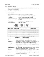
2.1.1
INPUT
RATINGS ................................................................................ 2-1
FIGURE
2.1.3
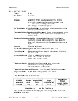
OUTPUT
RATINGS ............................................................................ 2-2
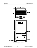
FIGURE
2.2
OUTLINE
DRAWING ........................................................................... 2-4
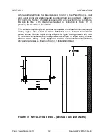
FIGURE
3.1
INSTALLATION
DETAIL
–
(MECHANICAL
CLEARANCES) ............... 3-2
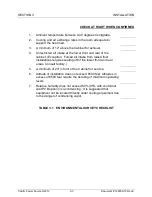
TABLE
3.1
ENVIRONMENTAL
SURVEY
CHECKLIST ............................................. 3-3
FIGURE
3.2
CRATING
AND
MOVING
OUTLINE
DRAWING .................................. 3-5
FIGURE
3.3.1
480
V
INPUT
CONFIGURATION ........................................................ 3-8
FIGURE
3.3.2
380
V
INPUT
CONFIGURATION ........................................................ 3-9
FIGURE
3.3.3
240
V
INPUT
CONFIGURATION ...................................................... 3-10
FIGURE
3.3.4
208
V
INPUT
CONFIGURATION ...................................................... 3-11
TABLE
3.6.1
INSTALLATION
WIRING ................................................................... 3-13
FIGURE
3.6
INPUT
TERMINAL
DETAIL ............................................................... 3-13
FIGURE
3.6.1
CUSTOMER
INPUT
WIRING
DETAIL .............................................. 3-14
FIGURE
3.7
OUTPUT
TERMINAL
DETAIL ........................................................... 3-16
FIGURE
3.7.1
OUTPUT
CONTACTOR.................................................................... 3-17
(CUSTOMER
LOAD
WIRING
DETAIL) ...................................................................... 3-17
FIGURE
3.7.2
OPTIONAL
OUTPUT
CIRCUIT
BREAKER ....................................... 3-17
(CUSTOMER
LOAD
WIRING
DETAIL) ...................................................................... 3-17
FIGURE
3.8.1
MULTIPLE
CABINET
SYSTEM
OUTLINE ........................................ 3-19
FIGURE
3.8.2
MULTIPLE
CABINET
SYSTEM
WIRING .......................................... 3-20
FIGURE
3.9
ELECTRICAL
SURVEY
CHECKLIST ..................................................... 3-21
TABLE
4.2
INSTALLATION
RECORD .......................................................................... 4-2
FIGURE
4.3.1
LCD
AND
INTERROGATION
SWITCHES .......................................... 4-5
FIGURE
4.3.2
MODE
SELECT,
EMER
OFF,
AND
START/RESET ......................... 4-15
FIGURE
4.3.3
FREQUENCY
SELECT
AND
VOLTS
ADJUST ................................. 4-16
FIGURE
4.4.1
SLAVE
CONTROL
MODE ................................................................ 4-20
FIGURE
4.5
CABINET
ASSEMBLY ....................................................................... 4-25
FIGURE
4.5.1
A
DISPLAY
PCB
ASSY.,
126072 ....................................................... 4-27
FIGURE
4.5.1
B
DISPLAY
PCB
ASSY.,
126172 ....................................................... 4-27
FIGURE
4.5.2
CONTROL
PCB
ASSY.,
126070
AND
126079 .................................... 4-29
FIGURE
4.6
CABINET
TOP
VIEW
-
FEATURE
CONNECTOR
DETAIL ................ 4-31
TABLE
5.1.1
6
MONTH
MAINTENANCE
CYCLE ..................................................... 5-1
FIGURE
5.1.1
REAR
OF
MS-SERIES
CABINET
–
BACK
PANEL
REMOVED ............. 5-2
FIGURE
5.1.2
UNDERSIDE
OF
MS-SERIES
INVERTERS .......................................... 5-2
TABLE
5.1.2
4-6
WEEK
MAINTENANCE
CYCLE .................................................... 5-3
FIGURE
5.1.3
FIRESCREEN
LOCATION
FOR
CLEANING ......................................... 5-3
FIGURE
5.1.4
MS-SERIES
MAINTENANCE
LOG ..................................................... 5-4
FIGURE
6.1.1
MAINFRAME ...................................................................................... 6-3
FIGURE
6.1.2
CONTROL
MODULE .......................................................................... 6-5
FIGURE
6.1.3
INVERTER.......................................................................................... 6-7
FIGURE
6.2.1
BLOCK
DIAGRAM
POWER
CONVERSION
CIRCUITS ................... 6-12


