


SECTION 6
SERVICE
Pacific Power Source ©2013
6-4
Document # 126050-10 Rev E
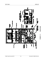
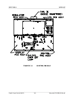
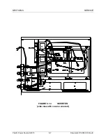
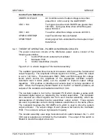
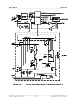
6.1.2 CONTROL MODULE DESCRIPTION
The function of the various assemblies and components of the Control Module is
described below. The numbers listed are to be used when ordering spare
assemblies and components. Refer to Figure 6.1.2 for the location of the
assemblies and components listed below.
1.
CONTROL PCB ASSEMBLY (P/N 126070 or 126079)
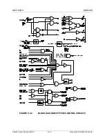
A circuit assembly which contains logic, comparator and oscillator
circuits. This board determines the state of the system and controls the
system function. It also contains a crystal-referenced local oscillator
which develops the output waveform. The oscillator output is a digitally
synthesized sine wave.
2.
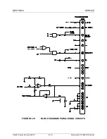
MODULATOR PCB ASSEMBLY (P/N 126071)
This circuit assembly receives the output of the oscillator and produces
the pulse-width-modulated signals required to drive the inverter
assemblies.
3.
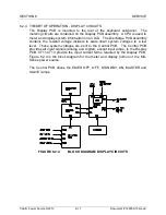
DISPLAY PCB ASSEMBLY (P/N 126072 or 126172)
This circuit assembly is mounted to the front panel and contains a CPU
which drives an LCD for metering, status, diagnostics and alarms. Two
RS232 serial ports are also available for a remote terminal or modem.
4.
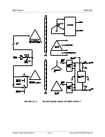
LVPS PCB ASSEMBLY (P/N 126074)
This is a smaller circuit assembly which is used to develop regulated ±18
VDC. This DC voltage is distributed throughout the mainframe and is
used to create low voltage DC for the control circuits on each PCB.
5.
COMPONENTS
C21 and C22, LVPS caps (P/N 720449-95)
S12 and S13, Push button switches (P/N 710023)
EMER OFF lamp (P/N 701024)
B1, fan (P/N 703104)


