SECTION 6
SERVICE
Pacific Power Source ©2013
6-6
Document # 126050-10 Rev E
6.1.3 INVERTER DESCRIPTION
The function of the various assemblies and components of the Inverter module is
described below. The part numbers listed are to be used when ordering spare
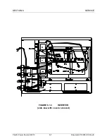
assemblies and components. Refer to Figure 6.1.3 for the location of the
assemblies and components listed below. Refer to Section 6.5.1 for removal and
replacement procedures.
1.
INVERTER ASSEMBLY (P/N 126225)
A 21kVA inverter assembly which contains the power circuits that convert DC to
AC and drives the output. The inverter assembly is housed in a metal case.
This inverter assembly has been designed to reduce RFI/EMI.
2.
DRIVER PCB ASSEMBLY (P/N 126270)
This PCB assembly receives control signals from the modulator, provides
isolation and then drives the power transistors. This PCB is a subassembly of
the inverter assembly.
3.
SNUBBER PCB ASSEMBLY (P/N 126272)
This PCB assembly is used to snub voltage spikes on the power transistors.
This PCB is a subassembly of the inverter assembly.
4.
COMPONENTS
C11-13, Feed through cap (P/N 720545-30)
C1-8, Filter cap (P/N 720096-10)
CT1, Current sensor (P/N 703130)
B1 and B2, Fan (P/N 703106)
R1-8, Snubber resistor (P/N 760180-10)
TAS1-4, Temp sensor (P/N 710039)
L1-12, Filter inductor (P/N 530014)

