


TABLE OF CONTENTS
Figure
Description
Page
Pacific Power Source ©2013
ix
Document # 126050-10 Rev E
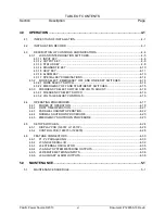
List of ILLUSTRATIONS and TABLES (continued)
FIGURE
6.2.2
BLOCK
DIAGRAM
SYSTEM
CONTROL
CIRCUITS ......................... 6-14
FIGURE
6.2.3
BLOCK
DIAGRAM
DC
POWER
SUPPLY ......................................... 6-16
FIGURE
6.2.4
BLOCK
DIAGRAM
DISPLAY
CIRCUITS........................................... 6-17
FIGURE
6.2.5
BLOCK
DIAGRAM
PARALLELING
CIRCUITS ................................. 6-19
FIGURE
6.3.1
PERFORMANCE
CHECK
FLOW
CHART ........................................ 6-22
FIGURE
6.3.2
LVPS
FLOW
CHART ........................................................................ 6-23
FIGURE
6.3.3
DISPLAY
FLOW
CHART .................................................................. 6-25
FIGURE
6.3.4
EMER
OFF
FLOW
CHART ............................................................... 6-27
FIGURE
6.3.5
NO-INVERTER-VOLTAGE
FLOW
CHART ....................................... 6-29
FIGURE
6.3.6
ABNORMAL
VOLTS
FLOW
CHART ................................................. 6-31
FIGURE
6.4.1
LVPS
SCHEMATIC ........................................................................... 6-32
FIGURE
6.4.2
INPUT
POWER
SCHEMATIC ........................................................... 6-33
FIGURE
6.4.3
DC
POWER
SUPPLY
SCHEMATIC ................................................. 6-34
FIGURE A.1 3060-MS MAINFRAME MAINTENANCE/SERVICEABLE PARTS
A-1
FIGURE A.2 3060-MS INVERTER ASSEMBLY MAINTENANCE/SERVICEABLE
PARTS
A-2
FIGURE B.1 MS3060 SYSTEM SCHEMATIC
B-1


