


SECTION 6
SERVICE
Pacific Power Source ©2013
6-11
Document # 126050-10 Rev E
Control Term Definitions
UNDER VOLTAGE
UV Condition exists if output voltage is less than
preset limit. Limit is set by the ALARM KEY.
VDC > 160
Term goes true when both BUSES are greater than
180 VDC. Term goes false when either Bus goes
below 160 VDC.
VDC > 240
True when either Bus voltage exceeds 240 VDC.
XFMR OVERTEMP
Input Transformer has overheated.
XFMR TEMP
Analog signal from embedded thermocouple in input
transformer.
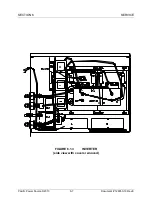
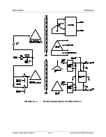
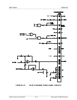
6.2.1 THEORY OF OPERATION - POWER CONVERSION CIRCUITS
The power conversion circuits of the MS-Series power source consist of the
following assemblies:
1.
Control PCB which contains the Oscillator
2.
Modulator PCB
3.
Inverter Assemblies (3 each)
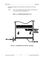
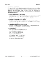
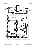
Figure 6.2.1 is a block diagram of the inverter assembly.
The oscillator generates three low level sine waves which are at the fundamental
output frequency. The amplitude of these signals is 4.8 VAC
rms
when the output
is set to 120 VAC
l-n
. Potentiometers R261, R262 and R263 supply DC voltage
levels which control the amplitude of the appropriate oscillator outputs.
Automatic Gain Control (AGC) can be enabled to improve output voltage
regulation. S14 enables or disables and selects local or remote operation of
AGC. When the Frequency Select Switch is in the EXT or SLAVE positions, all
outputs of the oscillator are disabled and will be 0 VAC.
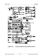
The oscillator output is fed to the modulator PCB which creates a pulse width
modulated digital signal, as required by the inverter assemblies. The modulator
also receives six current signals, two from each inverter assembly, which are
representative of individual inverter
assemblies’ output current. These signals
are used to guarantee current sharing between assemblies on the same phase.
The modulator develops the INV AMPS term which is used to drive the system
output ammeter. The output voltage of each phase is fed back to the modulator
PCB. This is done to achieve high waveform quality.
The inverter assembly uses large transistors which switch between the +/- 200
VDC power supplies as controlled by the modulator. The output of this switch is
filtered to create the output sine wave.


