SECTION 6
SERVICE
Pacific Power Source ©2013
6-13
Document # 126050-10 Rev E
6.2.2 THEORY OF OPERATION - CONTROL CIRCUITS
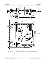
The Control PCB is mounted to the rear of the keyboard sub-panel and performs
the central system control of an MS-Series mainframe. This PCB monitors key
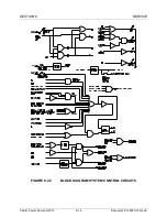
system parameters and either allows or prohibits operation accordingly. Figure
6.2.2 is a block diagram of the system control circuits within the mainframe.
When input power is applied and the input circuit breaker is closed the LVPS is
on. At this point, the Control PCB is performing preliminary diagnostics and will
light the red System Off LED on the front panel when all diagnostic tests have
been passed. The INPUT LINE FAULT signal will be at -12 VDC when all input
diagnostic tests have been passed.
If the machine has an internal fault the EMER OFF push button will light. After
the fault has been cleared, pressing the START/RESET push button will allow
normal operation.
Rotating the MODE SELECT switch to STANDBY and then pressing
START/RESET will turn on S7, the Slow-Turn-On Contactor. Resistors R1, R2
and R3 limit the inrush current during transformer turn on and charging of the
power supply capacitors. At this point the MODULATOR ENABLE signal is high
allowing the inverter to create sine waves at the output. When the power
supplies have charged S3, the input power contactor, will close. Rotating the
MODE SELECT switch to ON will close the output contactor, S5.
Rotating the MODE SELECT switch to OFF will open all input and output
contactors and cause the Discharge PCB to become active. The Discharge PCB
switches in a pair of resistors, R4 and R5, whose sole purpose is to discharge
the DC supplies.
Pressing the red EMER OFF switch will open all input and output contactors and
cause the Discharge PCB to become active. The emergency off flip-flop, Q6, is
also set.
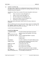
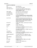
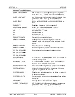
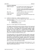
Figure 6.2.2 shows the various control signals used in the system. These signals
are named appropriately to aid understanding.

