
SECTION 6
SERVICE
Pacific Power Source ©2013
6-18
Document # 126050-10 Rev E
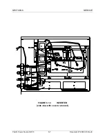
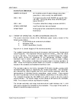
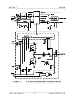
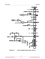
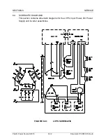
6.2.5 THEORY OF OPERATION - PARALLELING CIRCUITS
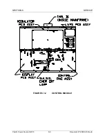
The paralleling circuits are located on the Control PCB. The Control PCB is
mounted to the rear of the keyboard sub-panel. The Master Cabinet's Control
PCB assembly is central to the system control of a Multi-Cabinet paralleled
system. This PCB monitors key system parameters and either allows or prohibits
operation accordingly. Figure 6.2.5 is a block diagram of the paralleling circuits
within all cabinets of the paralleled system.
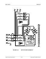
P1 and P2 are the paralleling connectors. Tying pin 18 and pin 19 together with
isolated external contacts shall cause an external emergency off of the system.
If a cabinet is a Master and in an EMER OFF state, it will cause all paralleled
cabinets to be in an EMER OFF state. The master EMER OFF must be cleared
first; then any slave EMER OFF may be cleared.
When all slave cabinets have no EMER OFF and the mode select switch is in the
ON position, the MASTER controls total system operation.
Each cabinet in a paralleled system generates its own inverter amps signal. This
signal is summed together to create the system amps signal. System amps is
total amps of the system and may be displayed at any cabinet.


